1. Structorizer
Welcome to the Structorizer User Guide
Editorial remarks:
- I (we) hope to offer you a detailed enough user guide for Structorizer, which is meant to be easy to use but has acquired a lot of features that might need some explanation.
- To keep this documentation up-to-date with a dynamically developing product is a bunch of work, so please understand that we can't manage to do this in several languages simultaneously. Though the product itself has several localizations, we hope that for the user guide English will do for most of you.
- If anyone of you wants to get implicated in this editorial challenge, just drop me a mail and I will give you access to the CMS.
- Among the potential users of Structorizer there may be programming experts who are fond of the clarity of Nassi-Shneiderman diagrams for algorithm design and documentation and just needed a convenient editor on the one end and absolute beginners just starting to comprehend what programming is about and were told to try their first steps in structograms (cf. Use Cases). How can a single user guide meet the expectations of so wide a scope of readers? Though the main focus is to describe how to use this software rather than teaching to program or the first things about computers, we will often have to go back to the roots. Yet, our aim to achieve an acceptable balance may not always seem successful.
- If you find some section difficult to understand then just inform us via mail or generate an issue.
The GUI (Graphical User Interface) of Structorizer is quite minimalist and simple to use (see image below). It is built of
- a Toolbar offering shortcuts to features and functions,
- the Menu, which provides most of what the Toolbar does and some more features,
- the Work area, which is where you create your NSD,
- the Report list where the Analyser component (if activated) writes warnings on dubious diagram contents (the related diagram elements may be marked with a red or blue triangle), and
- a Tabbed info pane on the right-hand side, presenting:
- Arranger index, which lists all groups of diagrams currently held in the Arranger tableau in lexicographic order (per group: main programs first, then subroutines, then includables);
- Code preview, where the translation of your current diagram into your favourite export language is simultaneously shown.
(Diagram work area, tabbed pane with Arranger index and Code preview, its currently selected tab, and Analyser Report list form a focus ring through which you may navigate with the <Tab> key in clockwise and with <Shift><Tab> in counter-clockwise direction. Within the tabbed pane you may change the tab with cursor keys. Report list, Arranger index, and Code preview may be disabled independently.)

Looks plain and simple (and is meant to be!), but yet "under the hood" there is a lot of functionality waiting for you to try it out.
The dialogs are localized in several languages you may choose among (either on the welcome dialog you see below or via the menu "Preferences › Language"):

If you find the product behaviour differing from this User Guide or some malfunction then please don't hesitate to report this as an issue (bug report). You are also welcome to propose functional enhancements the same way, if you think that some useful feature is missing.
1.1. About
Structorizer itself has been designed and coded by Bob Fisch and is published, since version 2, as open-source application under the terms of the GNU GPL 3, which means that everyone is free to change the code to fit their own needs as long as the header comments remain intact, so that each part of code can be tracked down to its original author.
For the license conditions you may also see the About page on the Structorizer home and the "License" tab in the "About" info box (accessible via menu "Help › About..." or key combination <Shift><F1>) in Structorizer itself:
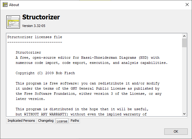
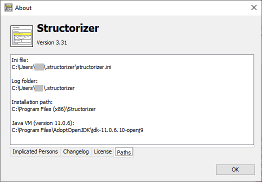
The "About" window also displays the following information:
- version number of the running application,
- the change history for this version,
- the names of the implicated developers and inspirers,
- the locations of
- the installed product (installation path),
- the used INI file (holding the configured preferences),
- the logging file(s),
- the Java home path (since version 3.30-17) and version:
1.2. Authors
Since September 2015, Structorizer is located on Github. Presently the following people are actively involved:
- Bob Fisch
- Kay Gürtzig
- Simon Sobisch
- Alessandro Simonetta
Concerning the software itself:
- Designed and developed by Bob Fisch
- Maintained chiefly by Bob Fisch and Kay Gürtzig
- Oberon source code generator coded by Klaus-Peter Reimers
- Perl and KSH export implemented by Jan Peter Klippel
- BASH generator written by Markus Grundner
- Java source code export developed by Gunter Schillebeeckx
- Subroutine call mechanism, visual runtime analysis, and more by Kay Gürtzig
- COBOL import by Simon Sobisch and Kay Gürtzig
- ANSI-C-99, Java, and Processing import written by Kay Gürtzig
- Arranger group management designed and developed by Kay Gürtzig
- Code preview, Javascript generator developed by Kay Gürtzig
- ARM code generator (prototype) by Alessandro Simonetta et al.
Concerning this user guide:
- First versions written by David Morais
- Corrections and supplements done by Praveen Kumar
- Recoded and extended by Bob Fisch
- Several pages added by Jan Ollmann
- PDF export by Bob Fisch
- Most pages, all recent additions and updates by Kay Gürtzig
Further details can be found on the "Implicated Persons" tab in the "About" info box (accessible via menu "Help › About..." or key combination <Shift><F1>) in Structorizer itself.
1.3. Versions
There are three series:
All these versions were coded in Delphi 6 PE and only work on Windows-based computers. Version "Light" 1.50 (not to be confused with 1.05) was a special one, because all the heavy features had been cut out.
For these versions the original Delphi code was converted and adapted to fit into a Lazarus (FreePascal) project. Since Lazarus runs on different operating systems, a Windows, Linux, and Mac OS X (Intel only) version had been published. Actually, these versions were somewhat buggy and have never worked at 100%.
Having had too much trouble with Lazarus, the code had been ported and completely rewritten into Java. These versions are no longer bound to any operating system and run as expected.
Since release 3.32, at least Java 11 is required to run Structorizer.
See a very detailed history on the changelog page.
1.4. Used Packages
The latest version of Structorizer uses the following packages:
The following package, which is used by the binary versions of Structorizer, is not contained in the source package:
2. Installation
Depending on the target operating system family, there are several ways to run Structorizer on your PC with or without an installation into the operating systems. No matter which way you choose, an appropriate Java installation (≥ Java 11 RE) is always a prerequisite (only in case of a package-manager-based installation the package manager will care for the presence of required software automatically). Oracle Java is not required, an OpenJDK RE will do as well (for troubleshooting in a Windows environment see Possible trouble with OpenJDK).
Roughly there are three opportunities to get Structorizer working:
- No installation or manual installation
You simply select the zip file that is suited for your operating system from the download page and save it in some appropriate folder. Now you may either drag it to the Application folder (Mac OS) or start the contained shell/batch script (Windows/Linux) or a simple launching wrapper (Windows). With Windows and Linux this is not even an installation but minimum-invasive while allowing you to derive some quickstart links, file-type associations or the like to facilitate launching.
Structorizer updates are not automatically installed but require manual interaction (downloading and unzipping the new version in place of the older one). In order to get informed about a newer downloadable version as soon as it is available you may enable the update search option.
Please refer to the respective subsection for details and recommendations how to proceed for a given operating system.
- Automatic installation via installer
- For Windows platforms, an attended installer is available for download. Please refer to the Windows subsection for details.
- While Java Web Start technology had still been supported (it is deprecated now and removed from Java 11 on!), you may have let Web Start handle the installation process. It was possible simply to click on the respective link. This does not work for Structorizer versions > 3.31-04 anymore, as these require Java version ≥ 11. The OpenWebStart project, however, aims to fill the gap for Java versions > 8 but requires individual installation.
- Automatic installation via package manager
For Debian/Ubuntu there is a downloadable package structorizer.deb, which can be installed with the Debian package manager (apt family). Please refer to the explanation for the Linux installation.
Automatic installations via installer will (in contrast to an installation-free use or manual or package-manager installation) involve an update mechanism that may ensure always to run the most up-to-date version that is available online. The Windows installer offers three different update policies (from always automatically to never checking) whereas the now deprecated Java WebStart would inevitably check for a newer version before starting (unless your computer is offline, of course). A Java WebStart installation may not always provide offline usage because it is held in the Java cache, which could have been configured to be cleared regularly. Both Java WebStart and Windows installer versions usually start a little slower than a manually unpacked Structorizer since they first check for a new online version (if configured so) and possibly download it.
Several manually unpacked local Structorizer instances (even of different versions) may coexist on a device, even with a Webstart installation and/or a Windows installer or package manager version, but they are likely to compete in the file type association (or even override the shortcuts of one another), so which of them would open if you double-click an *.nsd, *.arr, or *.arrz file may look like random.
When you use Structorizer the first time on a machine then you will be welcomed by the dialog pane already shown in the introduction and offering you the language choice and a beginner's mode (initially in English).
If you click on a language button then the Structorizer user interface will immediately switch the captions in the background, and even the welcome message is likely to be translated into the chosen language (here: German):

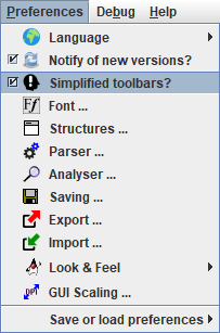
The lower part of the dialog offers a so called beginner's mode with slightly simplified menus and toolbars. The dialog will close with your click on one of the two buttons at the bottom. Which way ever you decide, you can always alter the mode via menu "Preferences ›  Simplified toolbars?" later on:
2.1. Windows
Use without installation
Download the latest version of Structorizer (Windows & Linux) from http://structorizer.fisch.lu and unzip it somewhere on your hard drive. Then simply run the contained file "Structorizer.exe".
The application will try to register the file types ".nsd", ".arr", and ".arrz" and to associate them with Structorizer in order to allow you opening Structorizer by a double-click on a file of these types later on (with the respective file already loaded into Structorizer).
If the launcher fails to establish these associations then the easiest mending is to double-click such a file and to bind "Structorizer.exe" via the dialog that will normally open: First choose to select the application from the list of installed programs and then — since Structorizer is not known to the registry — use the "Search..." button in order to locate file "Structorizer.exe" in your installation folder.
You may easily place a shortcut link on your Desktop if you right-click the file "Structorizer.exe" in the unzipped folder and then derive a link via the "Create Link" context menu item. Move the created link to the desktop, the start menu, or wherever you like, and rename it appropriately.
Trouble-shooting on start and in batch mode
If Structorizer fails to start (usually you should at least get an error message if something goes wrong) then it is most likely due to a missing or obsolete Java™ installation — remember that Structorizer is Java-based and the .exe file is just a wrapping launcher. Since Structorizer release 3.32 at least Java 11 is required! In order to find out what exactly is the problem you may open the console (e.g. by starting the "cmd.exe" program) and run the "Structorizer.bat" script file contained in the "Structorizer" directory. This way you should obtain the error description text, giving you enough hints to fix the problem. You might redirect the console output and error streams to log files directly by one of the following command lines (the first one for different log files, the second one for a common log file with both streams mixed):
Structorizer.bat 1> out.log 2> err.log
Structorizer.bat > allout.log 2>&1
(You may also have a look to section Logging but the Structorizer logging mechanism first requires Structorizer to have started at all.)
If Structorizer starts via "Structorizer.bat" without problems whereas a starting attempt via the launcher always reports the expected Java version to be missing then upto version 3.32-02 a possible explanation used to be that the launcher looked for a registry key the OpenJDK installation did not establish (see below).
The "Structorizer.bat" script is also helpful to generate source code from nsd (or arr/arrz) files or, the other way round, to derive nsd files from source files as batch task via the console or in a script (see Export source code and Import for details). Command "Structorizer.bat -h" prints a short synopsis of the possible batch command options.
Attended Installation (setup)
Download the "Windows installer with latest version" from http://structorizer.fisch.lu, which is a setup executable with name "structorizer.exe", then execute it locally. You may get a security warning, so make sure that the shown signatured publisher (should be: "Lycée des Arts et Métiers (LAM)" since version 3.32-12, in earlier versions: "Centre de gestion informatique de l'éducation") is valid. Some Windows versions may fail to display the publisher, though. If you trust the Structorizer makers nevertheless then go ahead, or use the manual installation (see above) otherwise. The setup will next offer you to install Structorizer either just for your account (which does not require administrative privileges) or for all users:
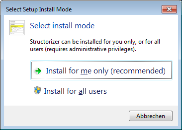
If you choose "Install for all users" then the Windows User Access Control (UAC) will request you to authenticate against an account with administrative privileges.
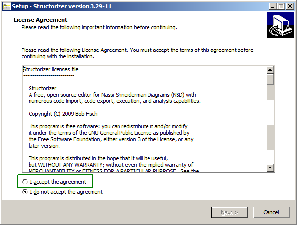
The installer will now present the license agreement, which you will have to accept in order to go on:
Afterwards you will be asked for the installation folder. The proposal you get depends on the chosen mode (the screenshot below shows an example of an account-specific installation with the fictitious user "whoever"):
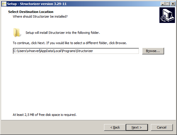
In case of an installation for all users you will obtain a different proposal, usually:

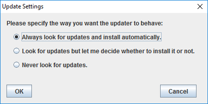
Now you will have the choice among three different update modes or policies (each represented by a slightly different ini file to be installed, the policy can be altered at any time after the installation via the system control, see further below):
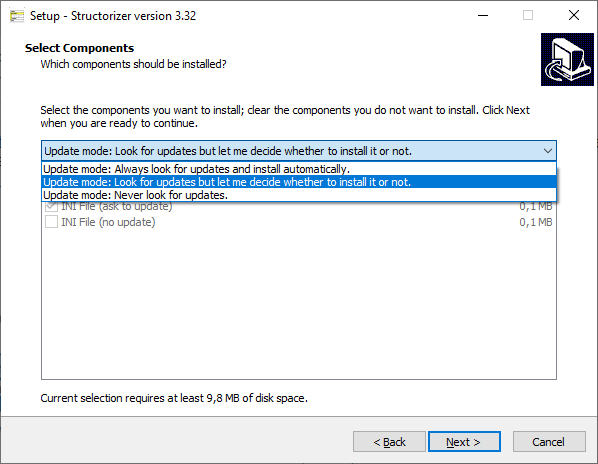
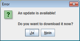
Whereas the first two policies ("Always ..." and "Look ...") will consult the product homepage on each start, the third one ("Never ...") won't do so. The update request with the second policy will look like this when a differing version is detected:
Note that Structorizer itself also offers a mode to check for newer versions (see preferences), which to activate doesn't make sense with this installation type because it would be redundant with the first two policies and would circumvent the third policy no matter whether you chose it in order to accelerate start or to preserve privacy. (The Structorizer-internal check is intended for use without installation.)
In the next step you will be asked whether you want a desktop shortcut (and maybe a quick-launch shortcut, too) created. When proceeding, the setup assistant will present you an overview of the made decisions and ask you whether to go on:
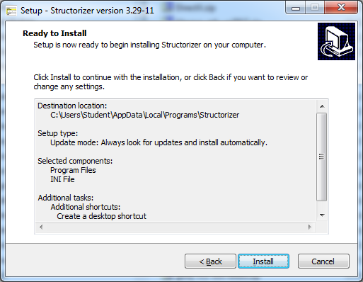
After having finished the installation you will be asked whether to launch Structorizer immediately or simply to exit the setup.
Remember: In order to launch Structorizer now, Java (at least version 11) must have been installed. If the launcher finds no or only an obsolete Java version, then a message box like the following one might occur:
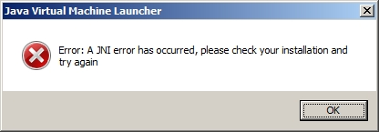
Note: If the installation assistant happens to request a 1.8.0... Java RE and to open the respective Oracle website in the browser at this point, the don't believe it and install a Java version ≥ 11 instead.
Otherwise, with the launch checkbox enabled, a splash screen (see screenshot below) will appear, the bottom text line of which will inform you about the next steps, which include:
- Testing local cache ... (is a Structorizer.jar file in place?)
- Testing network ... (can the Structorizer homepage be accessed?)
- Downloading ... (if the Structorizer homepage provides a newer Structorizer.jar file)
- Starting application ...

In the last phase (Starting application ...) a Java version test will be performed and it may report that the minimum required Java version for Structorizer is not available and then abort the launching process (since version 3.32-13), e. g.:
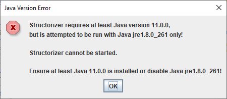
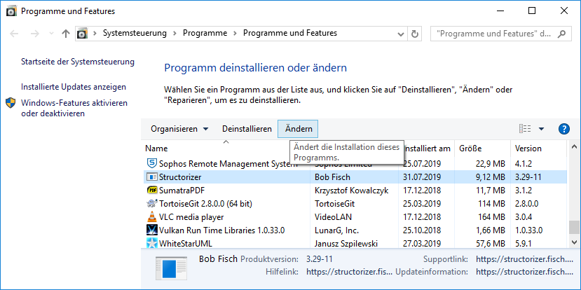
After a successful installation you will find Structorizer listed in the "Programs and Features" tool of the Windows Control Panel (the screenshot below shows it on a Windows 10 installation with German locale):
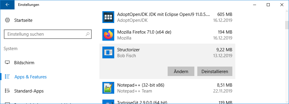
Alternatively, you may use the "Apps & Features" tool in the "System" category of the "Settings" menu in Windows 10 (again shown with German locale):
Either way, via the "Modify" button (labelled "Ändern" in the screenshots above) you may alter the update policy mentioned above (with an installation for all users this requires an administrative role):
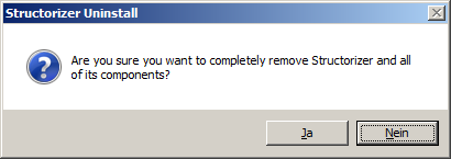
If you want to uninstall Structorizer, you ought to do it via the "Uninstall" button from "Programs and Features" (or "Apps & Features"), no matter whether Structorizer had been installed for all users or just for your account. The only difference is whether it requires administrative privileges. The uninstaller will first ask for your confirmation:
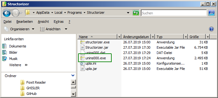
If you don't find the Structorizer entry in the "Programs and Features" tool, however, then you may go to the installation directory and execute file "unins000.exe" (marked with a green box in the screenshot below) directly. In case the installation directory is a system folder, you will have to execute "unins000.exe" as administrator.
If you happen to be oblivious about where you had installed Structorizer, you may always consult a running Structorizer instance launched via the installed shortcut. Just open the About dialog and select the "Paths" tab — the "Installation path" is what you are looking for, e.g.:

Possible trouble with OpenJDK environments
Since Oracle Inc. changed the license policy for Java, many users prefer (or were forced to use) an OpenJDK environment now. In many cases the mere unpacking of the binary package and a respective entry in the PATH environment variable as described e.g. in Tutorials24x7 may be sufficient to run Java applications.
Launchers like Structorizer.exe may first check for specific registry keys. Usually, the following ones will be probed in this order (where HKLM abbreviates HKEY_LOCAL_MACHINE):
- HKLM\SOFTWARE\JavaSoft\Java Runtime Environment
- HKLM\SOFTWARE\WOW6432Node\JavaSoft\Java Runtime Environment
- HKLM\SOFTWARE\JavaSoft\Java Development Kit
- HKLM\SOFTWARE\WOW6432Node\JavaSoft\Java Development Kit
- HKLM\SOFTWARE\JavaSoft\JRE
- HKLM\SOFTWARE\WOW6432Node\JavaSoft\JRE
- HKLM\SOFTWARE\JavaSoft\JDK
- HKLM\SOFTWARE\WOW6432Node\JavaSoft\JDK
The first of them existing and filled with entries might decide about the Java version used (so if a JRE of e.g. version 1.8.0_261 is installed and also a JDK of version 21.0.1.12 then it may be likely that Java 8 is used instead of Java 21).
If all are missing then environment variable JAVA_HOME will be checked (if it contains a valid installation path for a suited Java version then Structoizer is likely to open). If JAVA_HOME is also missing or contains an invalid path then the application will not start. Instead you would get an error message affirming the required Java version to be missing or inconsistent. To avoid this you should prefer an MSI installer package for the chosen free Java version, e.g. from Adoptium (or RedHat, which requires a registration, though).
When you decided for Adoptium OpenJDK, download the provided MSI installer for your OS version and make sure that the "JavaSoft" registry keys and the environment variable "JAVA_HOME" get involved in the installation (by default they are not selected!):
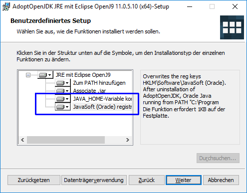
If you don't intend to develop Java applications yourself then you may prefer the leaner JRE (= Java Runtime Environment) installation (if available) over a full JDK (= Java Development Kit) since it is quite sufficient to run Structorizer and other Java-based applications.
If Structorizer still does not start then it is sensible to check the relevant registry keys (see above) and the JAVA_HOME environment variable. The latter is of course easier and less risky to modify than registry keys. (Be aware that you need administrative privileges to do these modifications if intended for all users. Moreover, you may have to restart the OS after the modifications in order to see an effect.)

A problem to keep in mind is that if you install an Oracle Java version (e.g. the obsolete Java 8 still offered as default by Oracle) after some OpenJDK then the Oracle installation assistant tends to wipe off all other registry key entries previously placed in path HKLM\SOFTWARE\JavaSoft and to overwrite environment variable JAVA_HOME, such that you might have to re-install OpenJDK Java versions ≥ 11 again in order to get them found.
2.2. Linux
a) Debian / Ubuntu
There is a package-manager installation: Download the Structorizer package for "Debian/Ubuntu" from the Structorizer download page. The name of the file is structorizer.deb. You may install it with the following command (maybe you'll need super user rights):
dpkg -i structorizer.deb
Note that from Structorizer version 3.32-12 on, you will need an up-to-date Debian version (12 or newer) in order to cope with the new compression algorithm used to generate the structorizer.deb file.
If no Java is installed, you will have to launch the following command to download and install dependencies (should the package manager confusingly ask for "default-jre | java6-runtime", whereas we need java11 at least, please don't panik—usually the default-jre is preferred and refers to an up-to-date Java version, e.g. openjdk17-jre, which will of course do):
apt-get -f install
Hint: On Ubuntu you may need to edit the file
/etc/java-11-openjdk/accessibility.properties
(or some more advanced version of it) and comment out the line starting with "assistive_technologies" by placing a # in front.
You may find further helpful information in German about Structorizer installation / usage with Ubuntu on the ubuntuusers Wiki.
Note that you can simply override a former installation of Structorizer if you install a newer version according to the step(s) listed above.
b) Linux distributions not accepting Debian packages
You may always choose to use Structorizer without actual installation (also under Debian/Ubuntu, of course): Download the latest version of Structorizer (Windows & Linux) from the Structorizer download page (the name of the file is structorizer_latest.zip) and unzip it somewhere appropriately in your file system (depending on whether you want to make it available for all users or just for yourself). You can simply run the file "structorizer.sh" contained in the unzipped directory. (Of course, you must have installed a suitable Java version, i.e., at least 11, before.)
If you'd like immediately to load a diagram upon application startup then just add its file path as argument to the command (you may even put several .nsd, .arr, or .arrz files as arguments at once):
structorizer.sh ~/nsd/myExample.nsd
See Batch Export and Batch Import for a complete list of available command line options for Structorizer. There is also a man page file "Structorizer.1" in the unzipped directory explaining the options and arguments for command line use. You may integrate it into the man directory or just view it using command (where <structorizer_folder> is to be replaced by the actual Structorizer directory, of course)
man -l <structorizer_folder>/Structorizer.1
2.3. Mac OS X
Download the latest version of Structorizer (Mac) from http://structorizer.fisch.lu and unzip it somewhere on your hard drive. There is no special installation package. It is just a bundled app. Simply drag the "Structorizer" application to your Application folder or run it from where you have unpacked the archive.
When you run Structorizer the first time, it will register the file types ".nsd", ".arr", and ".arrz" and associate them to itself, so you can doubleclick NSD files (.nsd) and NSD arrangement files (.arr, .arrz) later on to open them automatically within Structorizer.
3. Use Cases
There are several ways to use Structorizer as there is a variety of ways to use Nassi Shneiderman diagrams. Here we will show some paradigmatic ones in examples and give you advice for the recommended preferences to support these modes.
To keep it simple we will use a very little common task as example: To reduce all multiple blanks in a text to single blanks, e.g. let the input text be given as:
" This is a very airy string .",
then the desired result would be (note that single spaces are not removed, not even where they seem "misplaced"):
" This is a very airy string ."
These are the use cases we will discuss:
- The purist documentation approach — just structure with verbal, non-formal content;
- The initial design approach for external refinement (in a target language IDE);
- The design (and analysis) approach with stepwise refinement within Structorizer;
- The learning approach for beginners in programming;
- Structural analysis and documentation of existing software.
Note that this list of paradigms is neither exhaustive nor completely disjoint. Instead the items may be overlapping, borders fluent.
3.1. The Purist Documentation
Purist algorithm documenters often detest written code in Nassi-Shneiderman diagrams (and have their reasons to). They prefer pseudocode or even natural-language verbal descriptions of the steps to perform. In any case, it should be language-independent, where they mean that no specific programming language should be addressed.
On the other hand, verbal descriptions depend of course on some natural language and will usually be ambiguous.
We should be aware that algorithms are not restricted to mathematical or computational purposes. You might want to present an algorithm for building a house, for steering a car, for organising a wedding party, or whatsoever. Floating-point variables or trigonometric functions don't make sense there.
A possible purist (rather abstract) diagram for our (clearly computable) example task formulated in English might look like this:
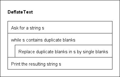
This approach is intuitively clear though we don't know how exactly the occurrence of duplicate blanks is to be detected and how to do the replacement.
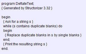
The purist might export the structure into certain programming language but then they are only interested in the translation of the structures and would like to preserve the elements texts, either by converting the instruction descriptions into comments or at least by suppressing any automatic attempts to transform the instruction syntax (since it is not executable code), e.g. the resulting Pascal export with the export preferences recommend below would look like this:
Most important activities:
Recommended preferences:
3.2. Design for External Refinement
Structorizer might also be used to start the design of an algorithm on a very abstract level in order to refine and accomplish the design in an external IDE for a specific programming language.
This approach ranges somewhere between the purist algorithm documentation and the Structorizer-internal top-down refinement (where most of the recursive refinement steps are done within Structorizer, possibly most of the way down to a working solution and only the final adaptation to a specific programming language being left for the target environment).
Actually this approach differs from the purist documentation chiefly in the export being an essential part of it, not only an option.
To facilitate the external refinement steps, a little twist is recommended in comparison to the purist documentation approach: All text placed into the diagram elements should be put into the comments fields from the very start. In order to do so, activate the "Switch text/comments?" mode. The advantage is that in this case verbally formulated conditions in Alternatives, Case elements, and loops etc. would not mix into the syntax on code export, either, but be separated as properly placed and marked comments instead.
The diagram, however, will look much the same as in the purist use case, though only while mode "Switch text/comments?" is active:
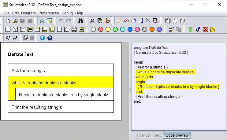
In the normal display mode, the elements would look empty:
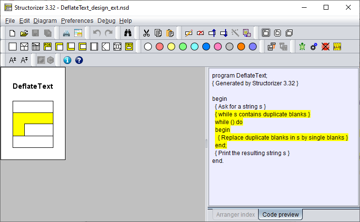
In display mode "Comments plus texts?" you would see the contents in the smaller comment font:
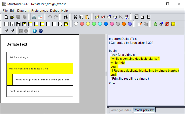
Most important activities:
Recommended preferences:
If some elements contain executable code:
3.3. Design with Internal Refinement
Another scenario is the algorithm design by stepwise refinement within Structorizer. You may start like in the Design for External Refinement use case but instead of immediately exporting the sketch you might switch to "Comments plus texts?" display mode and continue by filling in instructions that obviously implement the described steps:
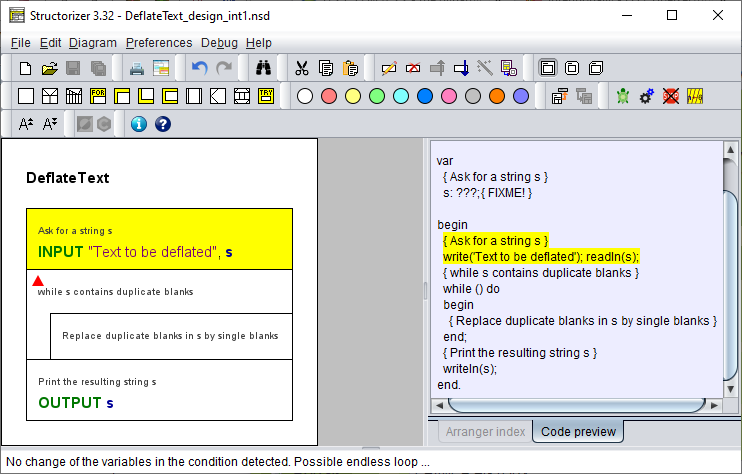
Note that the placed instructions above are not language-specific but both generic and executable in Structorizer. They will be translated to all supported export languages, usually.
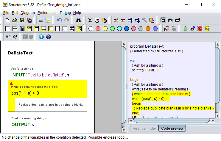
In some cases, expressions with built-in Structorizer functions or or built-in procedures may immediately fit. These are good for testing purposes but may not be portable to all export languages, however, so it is up to you whether you indulge to the temptation:
Where the implementation is more complex, the silver bullet will be a routine call, i.e. a delegation of the solution to a subdiagram. (It is most easily done by filling in a procedure call or assignment with function call, then transmuting the Instruction element into a Call element:
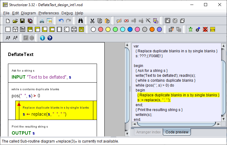
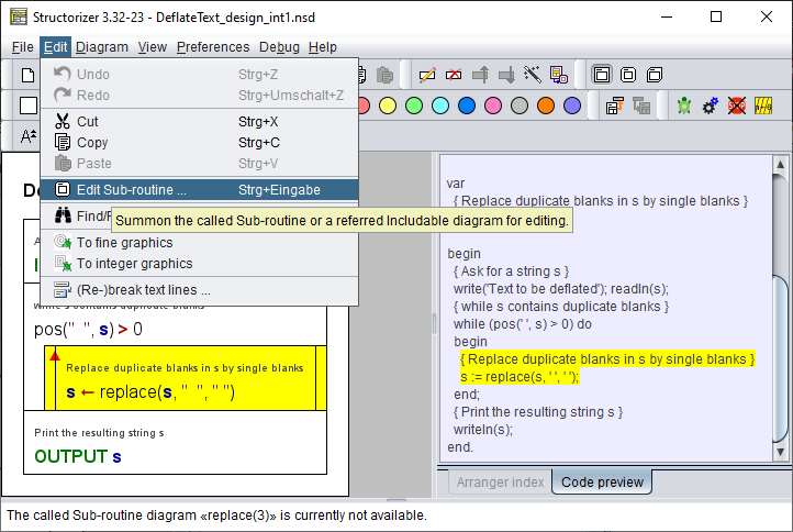
Now you might derive the required (and not of course existing) subroutine diagram by making making use of the "Edit Sub-routine ..." menu item (either from the "Edit" menu or the context menu):
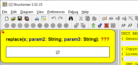
After having committed to the confirmation request, the derived routine diagram will be born with a rather generic header:
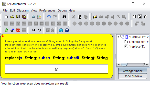
So you should complete the routine header and fill in the routine comment specifying its task and interface:
Then you might switch back to "Switch text/comments?" mode and start over on this refinement level, i.e. by decomposing the (sub-)task into steps described with expressive comments and so on until your intended level of refinement is achieved or all parts are implemented by executable elements:
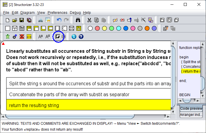
Most important activities:
Recommended preferences:
3.4. Programming for Beginners
Beginners will typically start with some simple mathematical calculations (say computation of the factorial, the greated common divisor or the like) in an IPO style based on immediately executable instructions without complicated syntax or with simple drawing tasks by means of Turtleizer primitives, where a reassuring success is easily achievable and provides a quick practical understanding of the algorithmic concepts. Observability via the animation facilities of the Debugger is as essential as the various hints of the Analyser.
Past this first, rather bottom-up style learning, the more experienced beginners' use case will not differ very much from the top-down Design with Internal Refinement use case - simply because this is usually the optimum way to solve a problem by means of an algorithm.
But in this case it is less important how compatible with a variety of programming languages the found solution may be than to achieve a working algorithm that can be tested and verified. The user will most sensibly have to adhere to the syntactical specifications of the Structorizer language dialect. That is why it makes sense to switch on Syntax highlighting and Analyser (see recommended preferences below).
With respect to our example task, the subroutine roughly sketched in the previous use case might be further refined until it gets completely implemented by means of instructions in executable Structorizer syntax, e.g.:
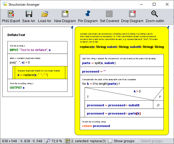
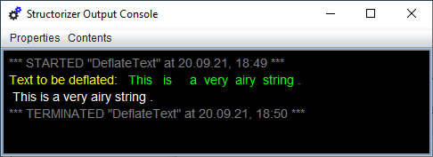
Now all kinds of test / debugging and run-time analysis (execution counting for hot spot detection or test coverage) might be explored to get a deeper understanding of algorithm behaviour:
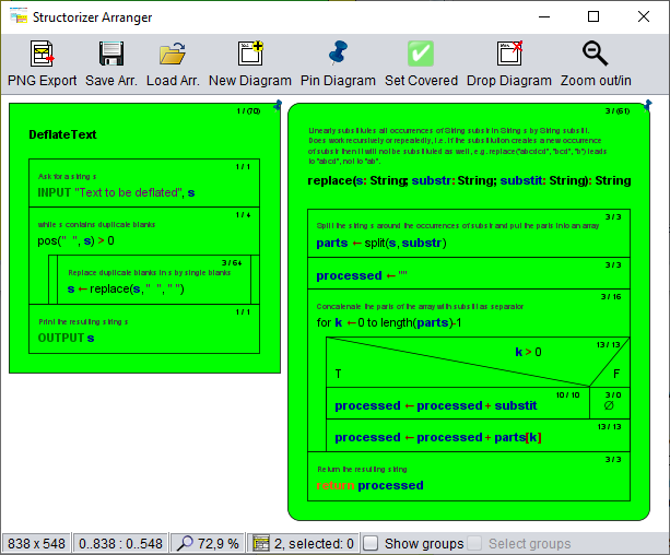
Test coverage proof for the above input (mode "deep test coverage"):
Visualisation for the test run emphasizing the execution hot spot — which operations are executed most frequently (mode "execution count"):
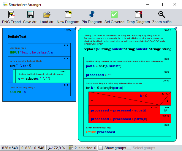
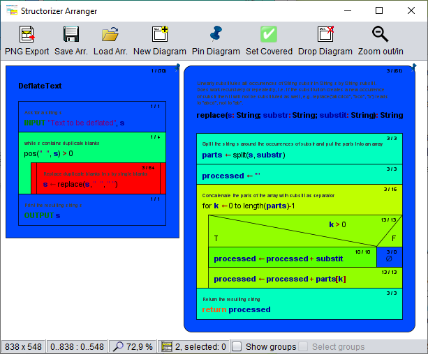
Visualisation for the test run emphasizing the logarithmic execution time distribution over the diagrams — what operation load hides behind a certain algorithmic component, e.g. a loop or a call (mode "done operations, logar."):
When the algorithm is validated and analysed then the task is basically done, lessons learned.
Of course it is still possible to generate code for the found solution, being aware that some parts of the algorithm will have to be rewritten in a chosen target programming language as there is not always a handy equivalent for all built-in data types, operators, functions, and procedures of Structorizer.
By deliberately choosing executable instruction syntax, Structorizer may also be used for rapid prototyping and demonstration of algorithms for more or less small exemplary tasks, particularly in teaching. Thanks to the integrated data structuring capabilities like arrays, records (structs), and even text files, this may also hold for certain algorithms in some more ambitious contexts.
Most important activities and tools:
Recommended preferences:
3.5. Structural software analysis
Rather an expert use case may be the structural analysis or documentation of existing software.
This kind of use aims at importing source code and thus deriving a graphical structural representation as group of related Nassi-Shneiderman diagrams. Possibly even a structural redesign might be a goal.
Typically the imported diagrams don't have to be executable in Structorizer (and won't be) but as far as possible a structural and semantical compatibility to the Structorizer syntax and philosophy can be deemed as helpful to store and represent meaningful diagrams.
Code re-export has been reported to be a sometimes desirable feature (at least for modest-size software), as a raw approach to code translation or cross compilation from one language to another via structograms, e. g. from Processing to Python.
Most important activities:
4. Elements
Here can you find explanations for the different kinds of elements that may be inserted into a Nassi-Shneiderman diagram and how to do this in Structorizer.
The framing Program (or Subroutine or Includable) element will already be there.
The body of any algorithm can be composed of up to ten standard types (plus an extra type) of elements all being offered in the element toolbar for insertion:

In order to add an element you must have selected either an existing element in your diagram or the initially empty centre of your diagram. When you click on the respective element button, an input form ("element editor") will appear, allowing you to fill in the element text and some comment. On committing, the filled-in element will be placed immediately after the previously selected element (see above). If you wanted to place the element before the selected element, you should just have held the shift button pressed while clicking on the element symbol in the toolbar.
Elements can also be created via menu "Diagram › Add" or the function keys listed among the key bindings.
To perform some (more or less atomic) action you will use the basic element type: Instruction ( ).
).
If you want to delegate complex operations to another diagram, insert a CALL ( ) instead.
If the further activities depend on a condition or selection, insert an IF ( ) or CASE (
 ) statement. They fork the control flow.
If you have to repeat some bunch of operations, you'll need one of the loop elements: FOR ( /
/ ), WHILE (
 ), REPEAT (
 ), or ENDLESS (
 ) loop.
If you happen to have to do several sub-tasks, which are mutually independent and could be performed in arbitrary order or in parallel, then you may choose to make them branches of a PARALLEL ( ) element.
If you are an advanced programmer and want to model exception handling then you may use the non-standard TRY ( ) element. You may "raise" (or "throw") an exception by means of an EXIT (Jump) element (
 ).
).
(An EXIT (Jump) element ( ) may also be used in certain cases to exit extraordinarily from a loop or a diagram, though it ought to be avoided.)
Just inspect the respective subsection for details.
Note: First of all the right choice and placement of elements is important.
If you are just interested in a symbolic representation of an algorithm then you may fill in arbitrary text of a natural language or pseudo-code and ignore the syntactic explanations given in the subsections. Still the text should be understood in a similar way: So if a condition is requested, the text should express a question or logical assertion.
If you want to test and export an algorithm, however, then of course you should adhere to the (still loose) syntactic recommendations.
If you want both, then there are modes in Structorizer that support a combined approach (e.g. Switch text/comments or Comments plus text).
4.1. Program / Sub / Includable
The bare diagram
When you start Structorizer or create a new diagram (via button  or key <Ctrl><N>), then you will be presented an empty diagram with dummy name "???" (the red triangle just flags the related Analyser hint in the bottom report list):
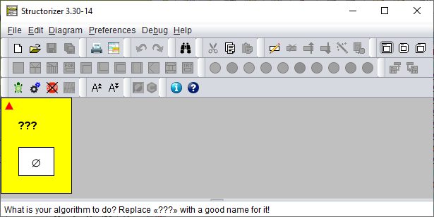
Double-click the question marks and fill in a sensible name in the upper text field superscribed with "Diagram name / function signature" of the element editor that will pop up.
- The name should represent the aim of your algorithm.
- The name should be an "identifier", i.e.:
- The name should not contain spaces: THIS IS NOT A GOOD ALGORITHM NAME.
- If the name is to consist of several words, you may fill the gaps between the words with underscores: THE_ALGORITHM_NAME_SHOULD_BE_CONTIGUOUS.
- Ideally, the algorithm name should start with a letter and contain only letters, digits and underscores (identifier syntax).
Also make sure to fill in the lower text field (superscribed "Comment") with a description of what the algorithm is good for and how to use it.
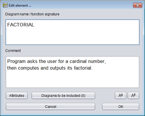
The framing (or root) element of a Nassi-Shneiderman diagram represents either a program, a (callable) subroutine, or an includable diagram (also see Type setting).
- A program or main means a standalone algorithm (an application) as being executable as a process on the operating system level. It usually communicates with the user via input and output instructions.
- A subroutine typically means a parameterised algorithm that can be used to perform some subordinate task within a program or another routine, e.g. to calculate the area of a circle with given radius, the volume of a cuboid, or the average (mean value) of a given list of numbers. Or you might want to draw a certain figure with the turtle several times at different places in the Turtleizer tool. Subroutines usually cannot access variables outside their scope but are provided with the values they need via parameters (on calling). On the other hand, they possibly return a result value to the calling level. Whereas subroutines like calculating the sine of an angle or the square root of a number are already built in (as is e.g. the rotation of the turtle by some degrees in Turtleizer), more complex subtasks may arise on decomposing an algorithmic problem. Then you will usually find it helpful to define your own subroutines, in particular if you have to perform them several times with differing parameter values. And you should decompose an algrithm that grows too large to keep the overview (structogams are not meant to rise to the size of a soccer field!). Depending on whether subroutines return a value or not, they are usually subdivided into
- procedures, not returning a value (and rather effectuating some impact to the environment);
- functions, supposed to return a result (usually without further impacts or side-effects).
- An includable diagram (as introduced with release 3.27) is typically a collection of constant definitions, type definitions, and declarations of variables, which are to be shared e.g. among a main diagram and some of its subroutine diagrams. In order to get hold of the defined data, a diagram must include the includable diagram by adding it to its include list, which is accessible via the button "Diagrams to be included" near the bottom of the editor (see screenshot above).
Structorizer allows you to distinguish visually whether a created diagram is meant to be a program, a subroutine, or an includable diagram — they differ in the shape of the surrounding box:
- A program diagram has rectangular shape,
- the corners of a subroutine diagram will be rounded,
- an includable diagram has two bevelled corners.
How to set the type of the diagram?
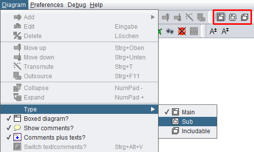
Just select the appropriate one of the menu items "Diagram › Type › Main" / "Diagram › Type › Sub" / "Diagram › Type › Includable" (see screenshot) or one of the toolbar buttons boxed red in the screenshot (cf Settings/Type).
When you start with a new diagram, it will initially be of the program type. The following images show you the computation of the factorial both as a program (left) and as a function (right). Note that the assignment to variable result is one of three supported value return mechanisms (see last paragraph below).
In order to allow you a subroutine simulation at the top level (i.e. without calling context), the Executor will pop up an input dialog for every function parameter before the execution and an output dialog showing the computed result on termination. (But this is only the case while you execute a subroutine diagram at top level.)
Diagram header
If the diagram is a program (main) or an includable diagram then the text field is supposed to contain just its name. A program name should be an identifier as described above, i.e. a word consisting of letters, digits, and underscores, beginning with a letter or underscore. It should not contain blanks.
A subroutine header, however, is supposed to contain more information than just the name. The subroutine name (an identifier as described above) is to be followed by a parameter list. A parameter list — in its simplest form — is a pair of parentheses containing a series of parameter names, separated by comma or semicolon (see example above).
- It may have Pascal syntax (where each parameter name is followed by a colon and a type name. The parameter specifications are to be separated by semicolons. If several parameters are of the same type, they may be grouped to a comma-separated list of their names, followed by the common colon and type name; note the semicolon between parameter groups! The result type — if any — follows the parameter list, separated from it by a colon), e.g.
functionName(var1, var2: Cardinal; var3: Double): Double
- Alternatively, it may have C/Java syntax (where the name of any parameter follows its type name; all parameter specifications are separated by commas, a grouping of parameters of the same type is not possible, semicolons are not allowed; the result type precedes the function name), e.g.
double functionName(int var1, int var2, double var3)
- It may also be expressed in BASIC-like syntax (very similar to Pascal syntax, except that the keyword as is to be used instead of the colon and neither parameter grouping nor semicolons are allowed) , e.g.:
functionName(var1 as Integer, var2 as Integer, var3 as Double) as Double
All three forms will be accepted by Structorizer and converted into proper function headers on code export if possible.
Structorizer allows so called overloading of subroutines, i.e. several subroutines may have the same name, provided their parameter numbers differ. Since typing of parameters (and variables in general) is neither mandatory nor even consistently forced if data types happen to be specified, Structorizer does not attempt to distinguish argument lists by argument types. Only the argument counts make a significant difference.
Be aware, however, that parameter order matters: This first argument value of a call is always assigned to the first parameter variable of the matching subroutine and so forth (argument assignment by position).
Since version 3.29-05, Structorizer supports optional parameters, as many programming languages (e.g. C++, C#, Python, VisualBasic, Delphi etc.) do. This means that a subroutine may be called with a shortened argument list, the call may omit some right-most arguments, in which case default values replace the missing arguments. If you want to make use of this opportunity you must specify the default values in the subroutine header — simply append an equality sign with a constant value (a value literal) to the parameters you want to make optional, e.g.:
double func1(int var1, int var2 = 3, double var3 = -8.7)
func2(var1, var2: Cardinal; var3: Double = 2.6E9): Double
It is important, however, that default values must be placed contiguously from right to left. Or, in other words, the first parameter you make optional requires that all subsequent parameters be optional as well. Likewise, a call may only omit a number of arguments from the end of the list, not inbetween (there is no cherry picking). The range of possible argument numbers for the call is shown in the symbolic signatures of the diagrams (as presented in the Arranger Index) — for the two demo functions above this would look like this (the parentheses contain the minimum and maximum argument numbers separated by a hyphen):
func1(1-3)
func2(2-3)
Return mechanisms
In order to return a value from a function diagram, you have the choice among three possible mechanisms supported by Structorizer (i.e. both execution and code export):
- Assign the value to a variable named exactly like the subroutine (like in Pascal; in the above example you might modify the last line to: factorial <- fact);
- Assign the value to a variable named "RESULT", "Result", or "result" (as shown in the example above);
- Add a return instruction (like in C, Java, and the like; modify the last line in the above example to: return fact).
The first two of the opportunities allow to override a provisionally assigned value by subsequent instructions such that just the last performed assignment to the function name or result variable will be the final result, whereas a return instruction will immediately force the termination of the subroutine with the attached result wherever it may occur and be executed.
You should not employ more than one of the three result mechanisms described above within the same diagram, otherwise the result is ambiguous and may not be what you expected it to be.
Note that mechanism 1 will cause Analyser complaints if option "Check that the program / sub name is not equal to any other identifier" is enabled in the Analyser Preferences.
Subroutine creation aids
Structorizer offers some helpful tools to facilitate the creation of suited subroutines along a top-down design paradigm:
- Menu item "Edit › Edit Subroutine" (to be applied on a selected CALL element; also available via the context menu or key binding <Ctrl><Enter>)
creates a subroutine diagram with matching interface if it hadn't existed before and opens it for editing.
- Menu item "Diagram › Outsource" (to be applied on a selected element sequence; also available via the context menu or key binding <Ctrl><F11>)
extracts the selected elements from the current diagram and converts the sequence into a subroutine, infering the required arguments and return values and replacing the sequence by a matching CALL element.
Includable diagrams (introduced with release 3.27)
The third diagram type differs from the types above in two important aspects:
- it shares its defined types, constants, and declared variables with all diagrams including it;
- it is executed at most once — from the first executed diagram that holds it in its include list.
Includable diagrams were introduced in order to:
- cope with code import and export of some source languages, where global definitions, include files etc. are a common feature;
- be able to introduce compound types (aka record, struct), which require a definition possibly having to be shared between a calling diagram and a called diagram if the argument list happens to contain a parameter of such a record type.
Whereas it is okay to share types and constants, it is not recommendable (though possible) to share variables this way. Indeed, the use of shared (global) variables should be avoided on algorithm design, because
- it hides the flow of data (if accessed bypassing the parameter lists),
- it bears always the risk of unwanted interference,
- it drastically limits the general usability of the algorithm.
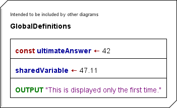
Example of an includable diagram, defining a constant, providing a shareable variable and writing a text once (only on the first include within a program execution):
Ideally, the diagrams to be included (the "includable diagrams") should only contain constant definitions and type definitions, and — if inevitable — variable declarations, variable initializations, and the like. The following example demonstrates that the constant ultimateAnswer defined in diagram "GlobalDefinitions" is recognized and therefore highlighted in the importing diagram "ImportCallDemo" as if it were introduced by the importing diagram itself (which is not the case because the preceding assignment "ultimateAnswer <- 3" is disabled — if it were enabled you would be warned of an illegal attempt to modify a constant).
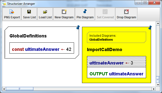
The right diagram displays the list of the names of diagrams to be included. The list is positioned above the program name or function signature and is surrounded by a bevelled box, which reminds the shape of an includable diagram.
The list of diagrams to be included is configured via the element editor of the including (dependent) diagram. Since release 3.29 you will find a button "Diagrams to be included (#)" at the bottom of the element editor. You may open the editor pane for the include list by pressing this button. Letting the mouse hover over the button provokes a tooltip displaying all include names:

The editor pane that pops up on pressing the button allows you to configure which Includable diagrams are actually to be included by the current program / routine / includable diagram. It contains a simple text area where you may write or modify the names of the diagrams to be included (separated by newline or comma). Above the text area, a pull down choice list and a simple "Add" button occur if Includable diagrams are available in Arranger for selection:
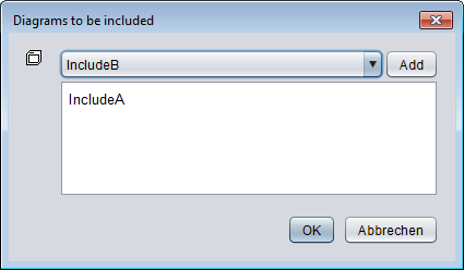
So you may choose the name of an available Includable and add it to the text by a click on the "Add" button. In order to remove an entry no longer wanted just delete it from the text area. If the entry you want to add is already in the text box then the "Add" button will not have an effect.
On this occasion it should be mentioned that included diagrams may (of course) in turn include other includable diagrams. This may even be necessary to ensure their order of execution in case of dependencies (if a diagram C includes A and B, and A must be read before B then B should in turn include A rather than rely on the order in the include list of C). But there must never be a cyclic inclusion (e.g. diagram A includes diagram B, which in turn includes diagram A)! Analyser and Executor do their best to detect and avert such a cyclic inclusion, however.
With version 3.30-15 Structorizer extended its service to facilitate the editing or creation of referenced diagrams from called subroutines towards included diagrams: When you select the frame of a diagram that has a non-empty include list then the menu items "Edit subroutine ..." in the "Edit" and the context menu alter their apperance and allow to summon an included diagram into a Structorizer editing context.
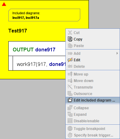
If the include list of the selected diagram contains more than one entry then you will obtain a request to choose among the listed Includables:
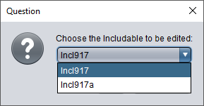
If the selected Includable name is ambiguous (several diagrams with same name in Arranger and group membership does not help to disambiguate them) then you will again be requested to choose among the existing diagrams (this time the choice list will show the file paths as well, because the name alone wouldn't help to tell them from each other).
Conversely, if there is no matching diagram in the pool then you will be asked whether you want to create the missing diagram:
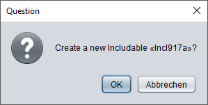
After having confirmed that, an Includable with the chosen name will be created and placed in Arranger. If the including ("parent") diagram had not been residing in the Arranger it will be pushed there as well, possibly a new arrangement group will be formed around both diagrams (if the parent diagram hadn't been member of some group yet). An additional instance of Structorizer holding the new diagram will pop up:

The new Structorizer instance will gain the focus.
Attribute Inspector
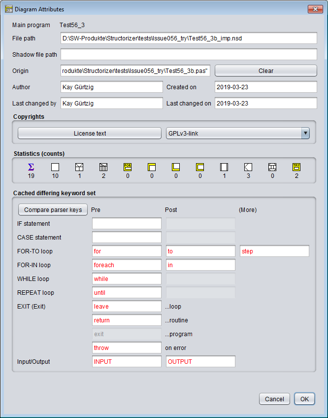
There is an "Attributes" button below the comment field in the element editor for Program/Sub/Includable, which opens an "Attribute Inspector" dialog where you may inspect more meta information about the diagram and set or modify some of them. For a new diagram, it might look like this:
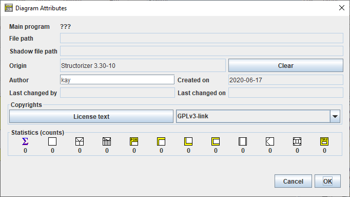
You may open this dialog also via the file menu ("File › Inspect attributes...") or with key combination <Alt><Enter> from the working area:
Since version 3.28-08, you may also activate the "Attribute Inspector" for any diagram located in the Arranger via the context menu of the Arranger Index (provided a diagram node is selected) or the Arranger itself.
The "Attribute Inspector" allows you to have a look at the meta information about the diagram, including paths, author, creation and modification dates, stored copyright information etc. It also shows you the counts of contained elements per type and it may present the differing associated keywords if the diagram was loaded without automatic keyword refactoring (as to be enabled in the Import Preferences):
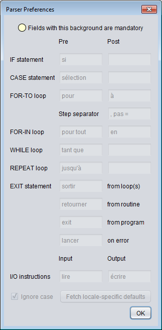
By pressing the button "Compare parser keys" in such a case you may additionally open the Parser Preferences window in read-only mode such that you can compare the current preferences with the ones attached to the diagram (particularly those marked red in the Attribute Inspector):
4.2. Instruction
Classification
An element of the type "Instruction" is the fundamental algorithmic element and may contain any command or simple statement.
Practically, there are five basic kinds of instructions (since version 3.26-02, mere variable declarations are also tolerated, release 3.27 additionally introduced the concepts of constant definitions and type definitions, see below):
- Input: An input instruction reads a text entered by the user and converts it to the value of a specified variable. An input instruction must begin with the input keyword defined in the Parser Preferences, which should be followed by one or (since version 3.29-03) more variable designators (e.g. identifiers, qualified names, or indexed array variables), e.g.:
INPUT value
INPUT length, width, height
INPUT date.day
INPUT readings[i]
If the input instruction comprises several variables then they are to be separated with commas. The targets of an input instruction will be registered as new variables if not already introduced before.
In order to provide the input with a non-generic prompt message you may place a string literal between the input keyword and the first variable (see diagram CIRCLE_DEMO further below, prompt string and variable may or may not be separated by a comma):
INPUT "Please enter your name ", name
An input instruction without variable is allowed (and will just wait for the user to press the <Enter> key as confirmation).
- Output: An output instruction prints something out to the user. An output instruction must begin with the output keyword as configured in the Parser Preferences. After the output keyword, a single expression or a comma-separated list of expressions is expected, e.g.:
OUTPUT "The result is ", value+9, "."
The expressions are evaluated and the text representations of their values will be written into a common output line in their order of occurrence. (Depending on the output mode setting in the Executor Control, the line might either occur in the Output Console Window or in a separate message box.) The next output instruction will not continue the same line but start a new line.
An output instruction without an expression is allowed and will produce an empty output line (or pop up a message box with the hint "(empty line)").
- Assignment: This is when a variable (naming a storage location) or some substructure of it is filled with a (new) value without user interaction. As a general rule, an assignment starts with a variable designator (usually an identifier, but might also be a valid access path with indices and/or component names), followed by an assignment symbol, and ends with an expression, the computed value of which is to be stored in the variable. Accepted assignment symbols are "<-" or ":=". (The first of them will be shown as a left arrow when drawing the diagram, see images below.)
Examples:
value <- 17
length := 9.3E4
date.day := 31
line[i] <- "This is just some string."
The very first assignment to a (new) variable is called an initialisation. Structorizer will not register a variable before it has been initialised (or targeted by an input instruction).
An initialisation may be combined with a declaration (i.e. an explicit type association), where you may choose among different syntactic styles (Pascal, Basic, C, Java):
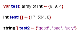
Note that such a "typed initialisation" (which is an effective instruction) is different from a mere declaration. The associated type will usually not be forced, i.e., you may override (or thwart) it by subsequent assignments.
- Internal procedure call (like e.g. forward(100) to move the turtle within the Turtleizer window, further procedures see Syntax). To call a procedure not being built in but referencing another diagram, however, it is suggested to use a CALL element rather than an ordinary Instruction element.
- A terminal return instruction used for the unconditioned delivery of a function result. "Terminal" means that it must be the very last and unconditional element (exit point) of the algorithm, i.e., it must occupy the entire bottom width of the diagram. The diagram must be of subroutine type (see Program/Sub and Settings). In any other case, a return statement must be placed in an EXIT (Jump) element (or be avoided altogether).
- Auxiliary stuff like declarations (of variables) and definitions (of types or constants) should preferrably be gathered at the very beginning of a diagram.
For a list of built-in operators, functions, and procedures usable within instructions (and other elements) see Syntax.
Example of an instruction sequence consisting of an input instruction, an assignment, and an output instruction (in two different display modes, with French keywords):
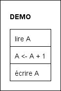
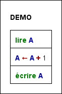
Standard diagram versus highlighted diagram
Example
Let us consider a somewhat more meaningful example now. Imagine you want to convert temperatures given in Fahrenheit to centrigrades. You know the formula as
ϑC = (ϑF - 32) · 5 / 9.
You will need an input instruction to ask for the temperature value in Fahrenheit before you can apply the calculation, and you may want to output the result afterwards. So the algorithm is a sequence of three instructions forming a main diagram according to the classical IPO model (input and output instructions inked green, the assignment instruction tinged yellow):
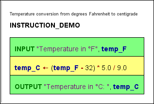
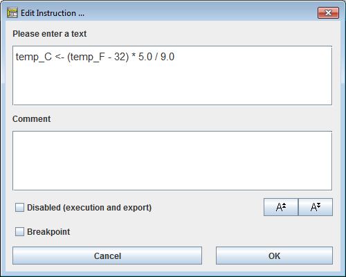
The input instruction implicitly introduces variable temp_F. Variable names in programming languages may usually not contain greek letters or subscripts, so we had to rename it. The yellow assignment instruction introduces the variable temp_C. As you see, the assignment contains the formula nearly as above with some inconspicuous but important differences, though: A variable means a named storage place that has to be filled with a value, therefore we need an assignment operator (the left arrow or ":=") rather than an equality sign to transfer the result of the computation into variable temp_C. The multiplication is expressed by an asterisk. For the division, we better make sure the numbers be interpreted as real (floating-point) numbers lest the result should be that of an integer division (which would eliminate fractions!); therefore they are better written with decimal points.
How to build this diagram, now?
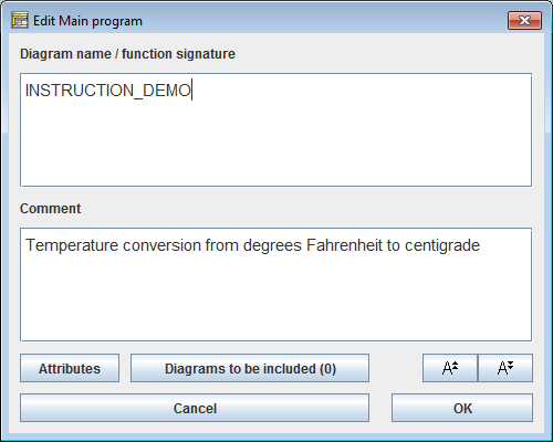
1. Start with an empty diagram, double-click its border and enter the name and a description, then commit by pressing the "OK" button:
2. Now select the (empty) diagram centre and double-click it or press the <F5> key or the instruction icon (empty rectangle) in the toolbar:
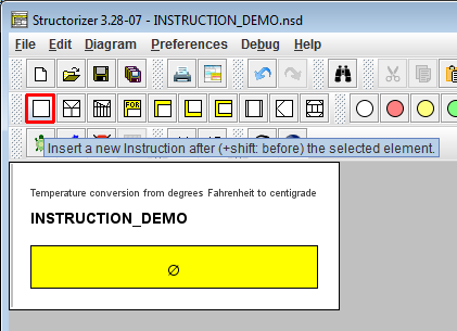
3. When the element editor opens, fill in the input instruction text — use the input keyword as configured in the parser preferences, optionally add a prompt string (here: "Temperature in °F") and specify the variable name, where we ought to adhere to letters of the English alphabet, underscores, and possibly digits:
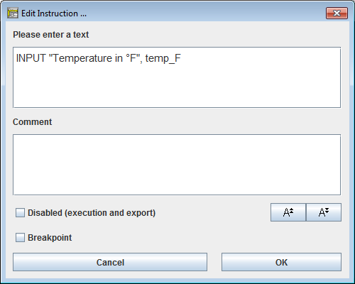
4. The just inserted element will still remain selected, so you may add the next instruction right away (again with <F5>, via the instruction icon, via menu item "Diagram › Add › After › Instruction", or via the respective context menu item, see step 6):
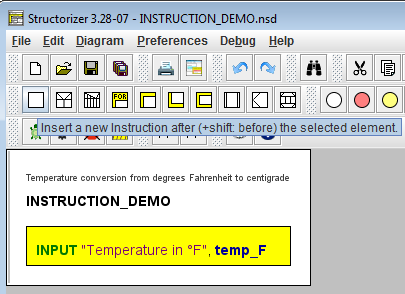
5. Fill in the assignment text (as outlined above, be aware of the assignment symbol between the target variable on the left-hand side and the expression on the right-hand side):
6. Now add the third instruction (e.g. via the context menu):
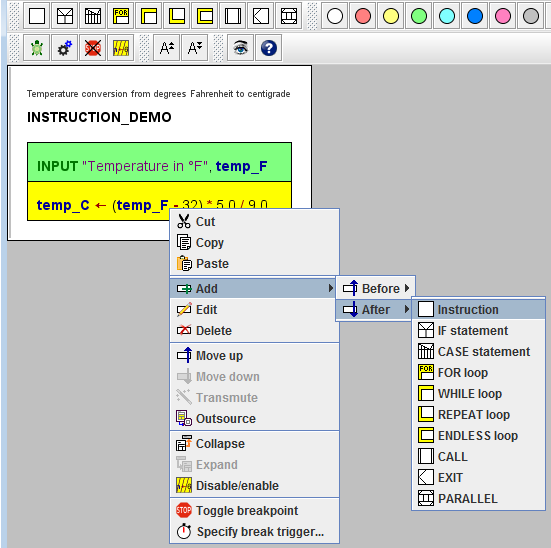
7. If you like, you may colourize instruction elements in order to emphasize certain aspects (by using one of the round paintbox buttons):
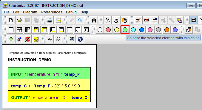
You may download the above Instruction demo diagram here.
Multi-line Instruction Elements
Usually, an Instruction element contains a single statement of one of the kinds listed above. For convenience, however, Structorizer allows an Instruction element to contain more than one statement. In the latter case, use one line per statement (in other words: place one statement per line). But be aware that e.g. breakpoints can only be attached to an entire element, not to a single line. It is not recommended to combine statements of different kind (e.g. input instructions with assignments or output instructions) within a single Instruction element. By the magic wand button  you may merge a sequence of selected Instruction elements into a single Instruction element or, conversely, split a multi-line Instruction element to a sequence of separate Instruction elements consisting of a single statement line each.
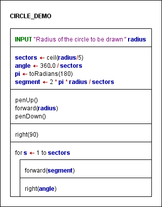
Since release 3.27 you may even spread long instructions over several lines, i.e., continue the statement text in consecutive lines by placing a backslash at the end of each line except the last one — see an example further below in subsection Type Definitions:
If you want to test your diagram via Executor or to export it to source code of a programming language then
- DON'T append instruction separators (like ";" or ":") to the lines;
- DON'T list several commands within a single line;
- DON'T let an Instruction element contain empty lines (obsolete since version 3.30-06).
Variable Declarations
Mere declarations with Pascal or BASIC syntax are tolerated as content of Instruction elements. To be recognised, a mere variable declaration (i.e. without initialisation) must start with one of the keywords var (Pascal) or dim (BASIC). After the keyword at least one variable name (identifier) is expected (or a comma-separated list of identifiers), then a separator — either : (Pascal) or as (BASIC) —, and a type name (identifier) or an array specification. It is not possible to construct an (anonymous) record or enumeration type in a variable declaration. Array specifications must refer to the name of a well-known standard type (like integer or boolean) or a previously explicitly defined type as element type of the array. Examples:
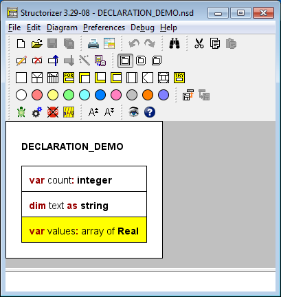
The type association by variable declarations is rather informal and not restricted to a certain programming language. Up to now, most declarations (with one important exception!) in Structorizer do not directly restrict the kind of value you may assign to a declared variable — you can always override the declared type by an assignment of a value of a differing type. But the declaration may influence code export and under certain circumstances be converted into a correct declaration in the target language. The code generators use some type name mappings and try to make sense of different ways to declare arrays.
The mentioned exception from type tolerance are the record types (aka struct types, also introduced with release 3.27). Since components of variables of these types are accessed via component names appended to a record variable name (the variable identifier is followed by a dot and the component name), the knowledge about the user-defined structure of a variable is essential for the parsing of expressions. Therefore type definitions had to be introduced (see below). Variables may not be used as records if they weren't explicitly declared with a previously defined record type (or at least initialised with a respective record initialisation expression), and declared record variables may not simply be abused for other kinds of values.
Note that variable names introduced by mere declarations will not be highlighted unless the variables are initialised somewhere.
Constant Definitions
Instruction elements may also contain constant definitions. Syntactically they look just like variable assignments but with a preceding const keyword. Semantically, constants are indeed handled like immutable variables by Structorizer. This means they can be set only once. The value may be computed by an expression. The Analyser may check whether all involved operands are literals, defined constants, or constant expressions themselves. Further attempts to assign another value to a constant or to alter the defined value will be prevented by the Executor. Structorizer guarantees the constancy in a generous way, though. So you may assign a complex constant object (say an array) to a variable. If you assign an array held by a variable to another variable then both would share the same object. Obviously, to do the same with a complex constant object would compromise constancy or make the target variable implicitly a constant. Rather than raising an error in such a case, Structorizer will just assign a mutable copy of the constant object to the target variable. This goes smoothly but ensures the expected consistency sufficiently.
Examples of constant definitions (also containing some variable declarations):
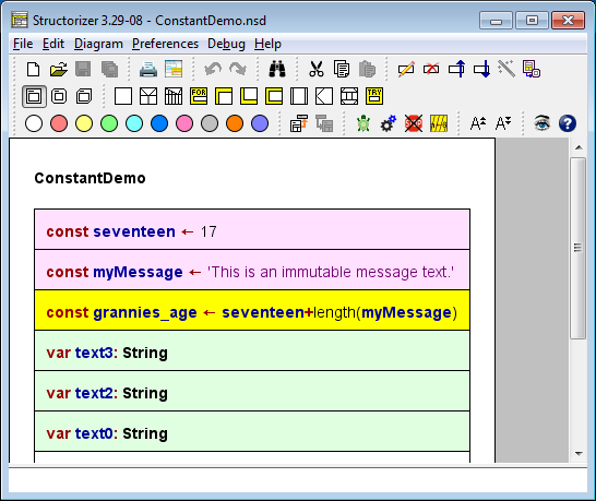
The formal parameters of routines may also be declared constant by placing a preceding const keyword. In this case, the value passed in from the respective argument on calling the routine may not be altered within the function (read-only semantics). Again, with passed-in arrays or records you obtain only an immutable copy, which prevents a compromising impact on the original array or record content.
The left-hand side of a constant definition (i.e. left of the assignment symbol) may also contain a type specification, thus looking like an initialising variable declaration but that the const keyword replaces the var or dim keyword. With the const keyword, even a C-like type specification would be possible (like in variable initialisations). As with variable declarations, type specifications are rather informal (and not restricted to type names of a certain programming language). Moreover, they are redundant here because the type may be derived from the constant expression. But they may yet be helpful on code export. Of course, the type association of a constant cannot be modified since a reassignment is not possible.
Type Definitions
Instruction elements may also contain type definitions. As outlined with the paragraph about variable declarations, they became necessary with the introduction of record/struct types and have been generalised for other kinds of type thereafter.
A type definition starts with the reserved word type, followed by the name of the new type to be defined (an identifier), an equality sign and, at the right-hand side of it, the type specification.
For a compound type, either the reserved word record or — synonymously — struct and an opening curly brace must come next. After the brace, a list of component declarations is expected, which look similar to parameter declarations of a subroutine; Pascal-style (name: type) as well as BASIC-style (name as type), and C-style (type name) component declarations are all accepted but must be separated with semicolon (!). Only in Pascal-style, group declarations are allowed: several component names sharing a common type may be listed with comma separation before the colon (e.g. Date components month, day or Student components name, firstname in the screenshot below). Finally, the declaration list is to be terminated with a closing brace (this syntax is a mixture from Pascal and C):
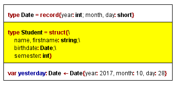
If you want to spread a type definition over several lines, then each line but the last one must end with a backslash.
The last element in the figure above shows a record variable declaration with immediate initialisation — which is highly recommended.
For an enumeration type (versions ≥ 3.30-03), the reserved word enum is expected (instead of struct or record), also followed by an opening curly brace. Between the opening brace and the closing curly brace (which ends the type definition), a comma-separated sequence of enumerator names (unique identifiers) is expected. Each of the enumerator names becomes an integer constant, the numeric value of which is incrementingly assigned by Structorizer, starting with 0. You may specify a different coding by associating an enumerator name with an explicit non-negative integer value via an equality sign (for an example, see second type definition in the screenshot below).
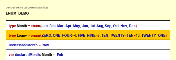
For an array type (as type definition supported since version 3.32-12), there are two ways to specify them on the right-hand side of the equaity sign in a type definition:
- Pascal style: it starts with the reserved word array, possibly followed by one or more index ranges within a common pair of square brackets, followed in turn by the keyword of and the name of the element type (or, recursively, another array specification);
- C-Style: the name of the element type (an identifier), followed by one or more brackets, each containing one or more non-negative integral numbers. The numbers specify how many rows (columns etc.) the array shall have.
Hence, a three-dimensional array type of floating-point numbers with double precision might be specified in any of the follwing ways equivalently:
- array [0..9, 0..14, 0..3] of double
- array [0..9, 0..14] of array [0..3] of double
- array [0..9] of array [0..14] of array [0..3] of double
- double [10, 15, 4]
- double [10] [15, 4]
Note: It is not allowed to define an array type over an anonymous compound or enumeration type construction. If you want to define an array type with e.g. a record type as element type then you must first define the record type (thus giving it a name), then you may refer to it via its name in the array type definition.
Last, but not least, a type definition may just name an alias for another type.
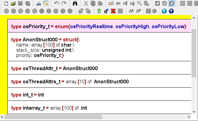
Defined types may also be used as parameter types for subroutines. But be aware that in this case both diagrams (the caller and the called one) must know the type, otherwise the argument passing wouldn't work. To share the type definition, you must place it into an additional diagram of type Includable and put the name of this includable diagram in the include list of both communicating diagrams (you have access to the include list of a diagram via the button "Diagrams to be included" in the Program / Sub editor).
4.3. IF statement
An element of type IF statement represents an alternative in the control flow. It is used at a decision point where the algorithm must take one of two different ways. The IF statement comprises the condition and both emerging paths. It is important to understand, however, that both branches join together again at the bottom of the element, i.e. after having passed the selected branch (whichever of them it is), the control flow will continue below the IF element in either case.
The text of the IF element is to contain the logical condition. It may be represented by any Boolean expression, i.e. an expression that evaluates either to true or to false. If the value computes to true then the left branch will be taken, otherwise the right branch.
Please note:
The labels for the "TRUE" and "FALSE" branch in the graphical presentation can be modified in Structure Preferences (menu item "Preferences › Structures").
But let us explain it with a simple example: imagine you have the task to find out whether an input value is greater than zero. This obviously requires first an input instruction for a variable, say A, and then a decision — you will have to compare the value of the variable with 0 and generate a different text output in both cases. This simple algorithm might look like in the screenshot below, where the entire IF statement including the branches is marked yellow (note that if you select an IF statement then only its "head", i.e. the upper rectangle consisting of the three triangles containing the condition and the branch labels will be highlighted, see step 5 below):
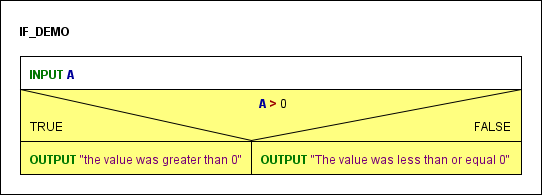
If the condition comes true then the OUTPUT instruction in the left-hand branch (labelled TRUE) will be executed, otherwise the one in the right-hand branch (labelled FALSE).
Now, how do you add an IF statement to your diagram? Assume the program is already named and the input instruction has already been placed (see Instruction):
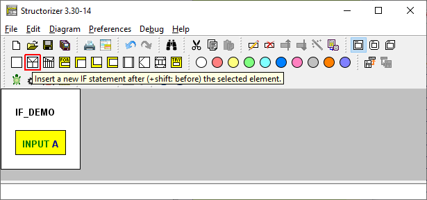
1. Select the element where you want to append an IF statement, then click on the IF statement symbol in the toolbar (or press the <F6> accelerator key, or use the "Diagram" or context menu):
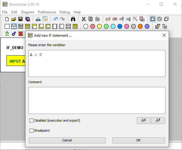
2. Insert the condition
When the element editor opens then the text field will contain some default string (which is configurable in the Structure Preferences). Replace this default string by the actual condition. This may be a comparison (via operators = or ==, <> or !=, <, >, <=, >=), a variable with Boolean content, or several conditions combined by logical operators.
Accepted logical operators are and (also &&), or (also ||), not (also !), and xor (also ^), where the latter stands for exclusive or (P xor Q is true if exactly one of the conditions P and Q is true). The logical operators may also be written with upper-case letters (AND, OR, XOR, NOT). In our case the condition is A > 0:
If one of the two branches is meant to remain empty (i.e. you are just going to create a "conditioned instruction") then formulate the condition in such a way that the non-empty branch is the "TRUE" branch, which is always on the left-hand side. (If you accidently did otherwise you may simply have the branches swapped and the condition negated by means of transmutation.)
3. Add the elements to be executed depending on the condition, e.g. Instructions, to the respective branches (see Diagram/Add elements) by selecting the (empty) branch and pressing the toolbar button for the intended element type:
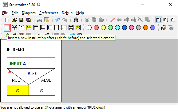
Fill in the element texts according to the algorithm you have in mind (see above).
4. If you want to have more than one instruction executed in a branch then simply add them after or before the first one (i.e., make sure to have selected an element of the branch when inserting or appending another one):
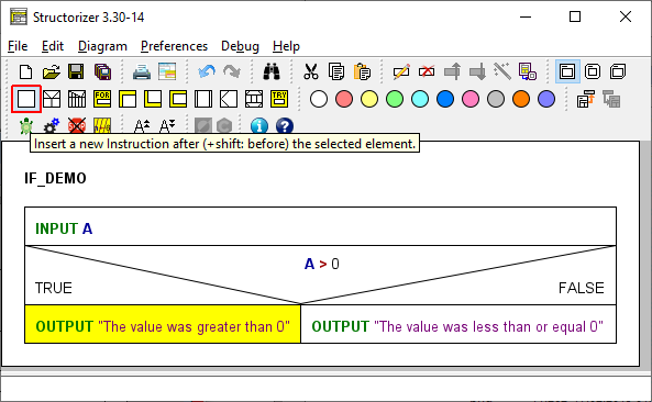
5. If you want to add further elements after the entire IF statement (remember that, no matter which branch was chosen and executed, the control flow will continue with the element following to the IF statement) you must select its head first:
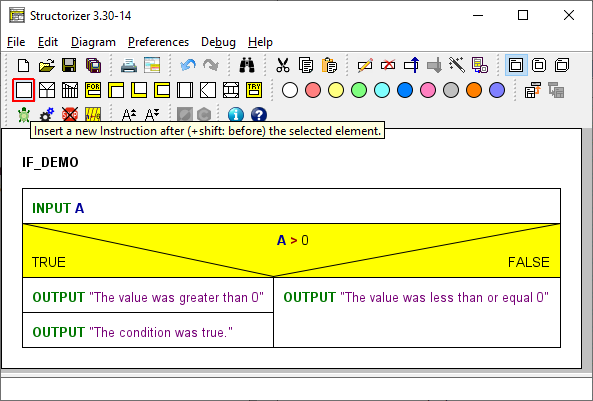
6. After the insertion of an unconditioned OUTPUT instruction beneath the IF statement (note that neither the INPUT instruction at top nor the — now selected — OUTPUT instruction are part of the IF element), the algorithm would look like this:
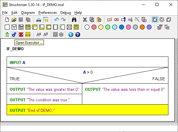
Download Demo
Alternatives (IF elements) may of course be nested (each IF branch may be a sequence of arbitrary elements, not only Instruction elements):
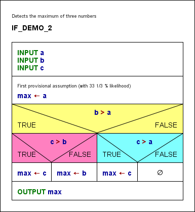
4.4. CASE statement
What is a CASE statement?
A CASE element (or "selection") represents a multi-way forking of the control flow within an algorithm. The branch to choose is determined by a comparison of the value of the control expression (discriminator) in the element header with the values (selectors) in the branch headings. The number of branches depends on the number of selector lines you write into the text field (see below). A CASE structure may provide a "ragpicker" branch (called default, else, or otherwise branch), which is placed right-most and will catch any discriminator value not matching any explicit selector.
In contrast to an IF statement, the controlling expression (discriminator) is not of Boolean type but typically yields an integral number or a character (in Structorizer it might also evaluate to a string), more generally spoken a distinguishable value out of a set of discrete (usually primitive) values. The selector values are then constants (literals) of that very data type to be checked against the actual value of the discriminator expression.
CASE elements are perfect for enumerator types but do neither make sense for floating-point numbers nor for structured objects, whereas there is simply no benefit over an IF statement for Boolean values, on the other hand. (Even if Structorizer is very tolerant here, if you intend a code export do not forget that many programming languages deny applicability to non-integral types. So better think twice whether you ignore the related Analyser warnings.)
Inserting a new CASE element
In order to add a CASE element select the element it is to precede or to succeed.
Then you may press the toolbar button marked with a red box in the screenshot above, or you might select one of the menue entries "Add › Before › CASE statement" or "Add › After › CASE statement" in either the context menu or the "Diagram" menu. (Or you simply press one of the function keys <F10> or <Shift><F10>, depending on whether the CASE element is to be inserted after or before the currently selected element.) This will open the element editor for a new CASE statement.
Since version 3.30-15, Structorizer offers you a specific editor for CASE statements, which is described further below. We will first explain the traditional editor variant because it elucidates best the structure of the (internal) element text and thus the default text that can be specified in the Structure Preferences. Which of the two editor variants will open depends on a checkbox in the Structure Preferences.
With the traditional general-purpose element editor, you get just a multi-line text area where the controlling information can directly be written and modified (which is of course convenient, particulary for a new CASE element):
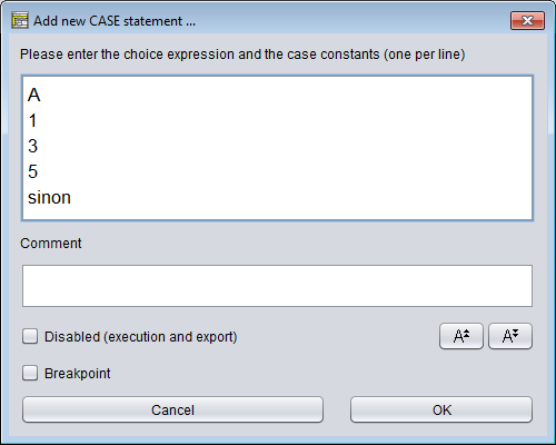
The multi-line text to be entered into a CASE form is interpreted like this:
- line 1: the discriminator expression to be evaluated (in the example above: variable A);
- lines 2..(n-1): one or more constant values (to be separated by commas) where the first match (i.e. equality) with the discriminator expression result will lure the execution into the associated (i.e. (i-1)th) branch;
- line n (the last line): the label for the "else" branch. (As outlined above, this is where the execution jumps into, when none of the selector constants from lines 2..(n-1) matches the discriminator result.) The label itself does not matter, unless you name it "%" (without the quotes, of course) — which would suppress the default branch. If you wouldn't place any instruction into the default branch then you can omit it (by writing the "%" into the last line).
On creating a new CASE element, the text area will be pre-filled with the respective text template you may specify in the Structure Preferences. (It must of course have the same structure.)
Remember: If you want a CASE statement without a ragpicker branch (aka "else part"), then the last line must be "%", otherwise a default branch will be provided and the content of the last line will be used as its label (no value check is done against it).
With many branches and/or long selector lines the CASE element might quickly become very broad. If long selector lines are the width-determining factor then you may use line breaking (i.e. split a long line into several ones by placing a backslash at the end of incomplete lines). See the last example in the table below.
Examples:
Content of the
CASE text |
Generated diagram |
A
1
3
5
sinon |
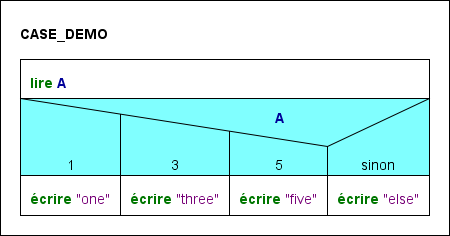 |
A
1
3
5
% |
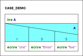
|
|
month
1,3,5,7,8,10,12
4,6,9,11
2
default
|
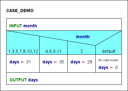
(Supported by Structorizer versions since 3.22-31)
|
|
answer
"yes"
"no"
"sometimes",\
"don't know"
default
|
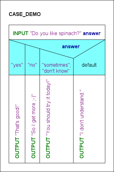
A selector line is broken via a (later invisible) end-standing
backslash in order to keep the branch width slim.
(Rotation of "atomic" CASE branches can be specified in
the Structure Preferences.)
|
After having filled in the text area of the element editor and committed ("OK" button), the result might look like in the screenshot below. You can now fill the different branches with suited elements from the toolbar:
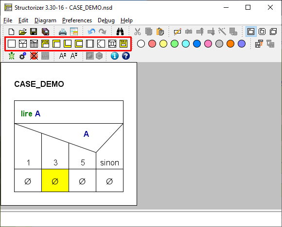
Download the accomplished Demo.
The drawn CASE structure is composed of
- the head (comprising the triangular shape showing the discriminator expression and the trapezoid shapes containing the branch selectors) and
- the respective branches, which are initially empty sequences (indicated by the ∅ symbols).
In order to insert elements to a branch select the respective branch and insert the elements needed in the usual way (see Diagram/Add element).
In order to append an element after the entire CASE statement select the head of the CASE structure first and then add the element to follow as usual (see Diagram/Add element).
Regarding the control flow, to pass a CASE element means to evaluate the discriminating expression and to execute the branch the selector of which matches the discriminator value. After the branch has been executed, the control flow passes to the next element appended below the entire CASE element — independent of the selected branch. If none of the selectors equals the choice value then without a default branch the control is directly passed to the subsequent element, otherweise the default branch will be executed first. (An empty default branch is redundant.) Note that an omitted default branch may make a difference on test coverage check (see Coverage Rules within Runtime Analysis).
Editing an existing CASE element
On editing an existing CASE element (e.g. after double-clicking or pressing the <Enter> key while the CASE head is selected) you may of course insert or remove lines as described above. You should be aware, however, that branches are associated with the lines. In contrast to a new CASE element, these branches will usually not be empty but will already contain instructions or other elements. Using the traditional editor (see above), the branches will not move correspondingly when you e.g. insert new case lines. Instead they will stick to their original position (left-bound) rather than to their originally associated selector list! (The same applies to possibly associated branch selector colours.) Regarding the first example of the table above, to insert a new line "2" between "1" and "3" would result in the following situation where the red-coloured branches are now associated to wrong selectors and will have to be moved rightwards by dragging them one by one or by a sequence of manual cut and paste actions in order to restore the original semantics:
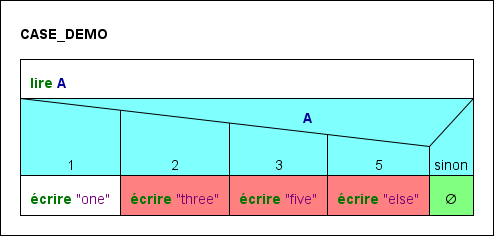
Conversely, if you reduce the number of case lines then the supernumerous branches from right to left will automatically be deleted on commit — no matter which selector lines you removed. Hence, if you had deleted the line "1" in the original example you would end up with the former default branch gone and all three remaining branches being wrongly associated (marked with red colour again):
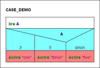
So take care when editing by means of the general-purpose element editor! If you want to avoid hassle then add new cases preferably near the end of the list (though the default case must always be the last one) and copy the contents of branches prone to vanish before you start to remove obsolete selector lines from the text.
Now this is where the CASE-specific editor comes in! It has been available since version 3.30-15 (and was substantially enhanced with version 3.30-16). It gives you consistent control not only over the selector lines but also over their associated branches (and branch head colours, too, by the way):
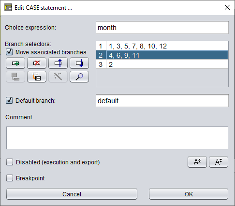
As you may see:
- The discriminator expression (i.e. the first line of the CASE text) has an own text field here (labeled "Choice expression:").
- Each selector line of the text is now represented in a table row (in the second column) beneath the descriminator text field (label "Branch selectors:"). The first column of the rows is reserved for branch numbers. It will show the sequential number of the associated branch — if the branch is not empty. An empty branch is represented by an empty cell. (So for a new CASE element, the cells in the first column will always be empty.)
- To the left of the table view you find:
- a checkbox "Move associated branches" (not enabled on creating a new CASE element) and
- eight function buttons, which are described below.
- The next section below contains
- a checkbox to enable / disable the default branch and
- a text field for the default branch label (only editable when the checkbox is selected).
Broken lines (by means of a backslash at the end of a line, symbolising the logical continuation in the next line, see last example in the above table) are concatenated into a common table row, where the "soft line breaks" (i.e. the backslashes) appear replaced by "\n" substrings between the concatenated line parts (see first table row in the following screenshot). Consequently, if you want to "soft-break" a line, insert the character sequence "\n" (without the quotes) at the intended position of the row. (Inside a string or character literal, if being part of a line, however, the newline escape sequence will just denote a newline character, as usual.)
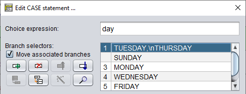
The effect of the first four buttons is straightforward:
 Adds a new selector row at the end of the table and opens the cell editor. New rows will always have an empty cell in the first column (no associated branch). From version 3.30-16 on, however, you may manually associate an orphaned branch (if there is one) to it by clicking into the cell of the first column and choosing the respective branch number.
  Deletes the selected rows.
 Moves the selected rows one row up.
 Moves the selected rows one row down.
The other four buttons need a little more explanation:
 Merges the selected rows into one (using comma as separator between the selector expressions) — will only be enabled if the selected rows are not associated to different non-empty branches (i.e. at most one branch number may occur among the rows, possibly several times, though).
 Splits the selected row into several ones (one for each listed selector expression) — will only be enabled if a single row with more than one comma-separated selectors is selected. If a branch number is associated then it will be copied to all emerging new rows (these rows could be re-merged as they share a common branch number).
 Enumerator assistant: It will be enabled as soon as the discriminator expression (first text field) is detected to be of an enumerator type and if some of the enumerator values are missing among the selectors. If pressed then rows for all missing enumerator values will be added (by the symbolic name). Moreover, occurring integer codes within the enumerator type range will be replaced by the respective symbolic enumerator names, and superfluous rows (only specifying values not being member of the enumerator type) will be removed — unless they are associated with a non-empty branch (i.e. a branch number). The action includes the unselecting of the default branch checkbox — a default branch is not of course needed if the set of selectors is exhaustive (except perhaps for paranoia).
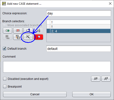
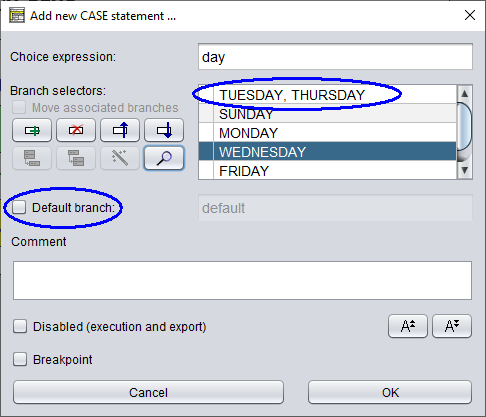
Note that the above example (where the former third row survived as new first row but with the enumerator names instead of the codes) requires the variable day explicitly to be declared with an enumerator type, otherwise the static type inference would not have succeeded:
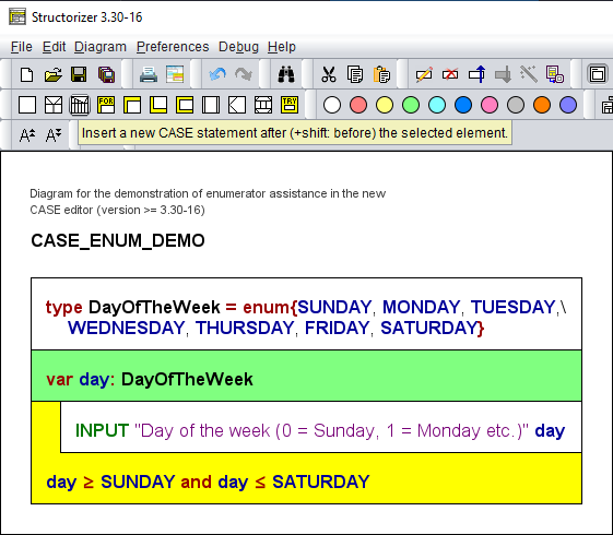
 Consistency check: Dynamically indicates the analysis status and allows to present a problem report (on pressing the button, content see below). It will change its colour depending on the findings of the automatic synchronous checks:
- It will turn red if conflicts among selectors are detected (i.e. a selector value occurs twice or more often) or if the discriminator expression is proven to be unsuited i.e. specifying an array or record.
- It will turn orange if non-empty branches get orphaned (bound to be deleted on committing), if some selectors cannot be evaluated (i.e. they do not represent constant expressions), or — in case of an enumerator type — if there are rows containing selectors that are not members of the enumerator type.
- Normal if none of the above problems were found.
The possible consistency problem reports have the following form:
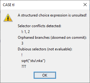
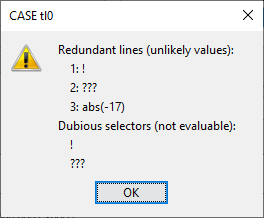
- Choice value of structured type
Just the respective message:
A structured choice expression is unsuited!
- Selector conflicts
Each conflict is symbolised by a line starting with the selector expression (character sequence), then a colon as separator, followed by the list of the row numbers of its occurrence (the same row number may be listed several times, if the value happens to repeat even within a line), e.g.:
4: rows 2, 3, 3, 7
- Dubious selectors (not evaluable literals or expressions)
A vertical list of the selectors as are, e.g.:
!
???
sqrt("idiotic")
- Missing enumerator values (and no default)
The names of the missed enumerator constants are shown in a coma-separated line (if the choice expression is not of an enumerator type or the selection has a default branch, this check will not be performed), e.g.:
BLUE, YELLOW
- Redundant rows (unlikely values) in case of an enumerator as discriminator
For each redundant row the row number and the selector line content are listed, both separated by a colon.
17: stan, laurel
- Orphaned branches
A comma-separated list of branch numbers no longer assigned to a row:
2, 5
Some more check examples:
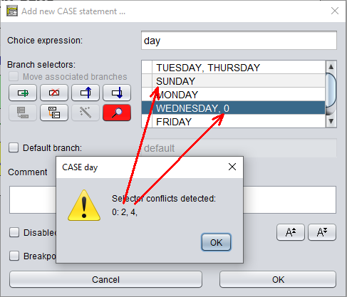
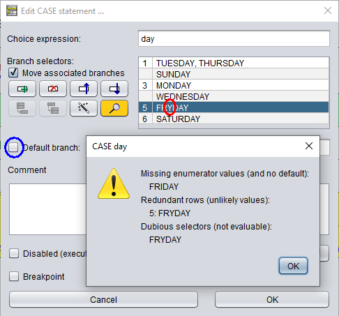
The table cells of the first column (branch numbers) are editable under certain circumstances from version 3.30-16 on: In this case you will get a pulldown choice list offering you:
- an empty string — if the cell contains a branch number then you would clear it (thus unbinding the branch);
- the numbers of all currently orphaned branches — thus allowing you to adopt one of them to the selected row;
- the already associated branch number (if any) of this row — to allow you to retain or restore the branch association.
Note:
- All activities to unbind or reassign the branches as described here are only sort of a pre-selection and will only be accomplished on committing the changes via the "OK" button. The status of the checkbox "Move associated branches" would not have an actual effect before committing, either. If it is unchecked on committing then none of the prepared branch reordering will be set into force — instead the result would be the same as if you had worked with the traditional editor (see above). So it is still up to you.
- The checkbox "Move associated branches" is not enabled on inserting a new CASE statement — simply because there cannot be branches containing elements, hence there is no need to mind their order.
This editor variant can be enabled (also conditionally, i.e., only for CASE elements with non-empty branches) or disabled in the Structures Preferences dialog.
Hints
- You may decompose a CASE element into an equivalent set of nested IF elements simply by applying the transmutation wand
 to the element in the diagram (not in the CASE element editor!). You may undo this decomposition but you cannot transmute nested alternatives into a CASE element. (The efforts to check the prerequisites for this conversion would be too expensive.)
- An option in Structure Preferences allows you to specify that atomic or collapsed branches in CASE elements comprising many branches (i.e., the number of branches exceeds the specified threshold), will be rotated in order to reduce width. See examples in the table above and in Structure Preferences.
4.5. FOR loop
Loop styles
An element of type FOR loop is used to repeat certain instructions a pre-determined number of times. Structorizer supports two varieties of FOR loops:
- COUNTING loop — the traditional style. The loop increments (or decrements) a number between an initial and a final limit of an interval. It is said to count the executed passes through the loop. Consequently, you have to specify a counter variable as well as its initial and final value. By default the counter variable is automatically incremented by one after each execution of the loop body.
You may specify a different increment (step value), which might be negative but it must be a non-zero integer constant if you want your loop to be executable or sensibly exported to a programming language of your choice. All these parameters form the control phrase, separated by configurable keywords.
Examples for counting FOR loop headers:
for i <- 1 to 15
pour j <- 10 à -10, pas = -2
- TRAVERSING loop — the loop body is repeated for every single element of a given collection. The elements are not required to be numbers, they may be of any data type. Therefore you will have to specify a variable representing the current element, and of course a collection, which will have to be an array, obviously. (See Executor for details how array variables and array expressions are used in Structorizer.)
Examples for traversing FOR loop headers (more examples further below):
foreach elem in {"good", "better", "best"}
para numero en numeros (where numeros should be an array variable)
The underlined keywords (or key string sequences) disambiguating and separating the parameters of the loop are configurable in the Parser Preferences.
This is how you may add a FOR loop to your diagram:
1. Select an element in your diagram after (or before) which you want to insert the FOR loop:
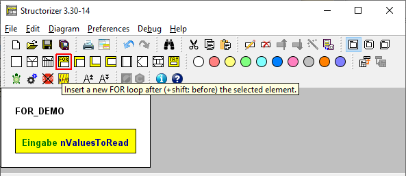
2. Now either select the FOR loop symbol in the toolbar (see red box in the image above — note that the FOR loop symbol, and likewise its appearence in the diagram, may look different, depending on whether or not the DIN representation is chosen) or open the context menu, choose the "Add" submenu, then either "Before" or "After", and eventually select the respective FOR loop entry. Alternatively, you may press the <F7> or <Shift><F7> key (see Keybindings).
3. When the editor pops up, you will see the following form. The screenshot shows it prepared for specifying a counting loop (upper radio button selected). The labels and default field contents are influenced by both Parser Preferences and Structure Preferences (we will discuss his later). Now you have several ways to set up your loop.
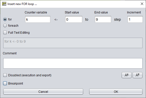
a) Fill in the text fields in the form region marked by the green box in the screenshot below. For a counting loop give the counter variable a name, specify its initial (start) value and its final (end) value. In addition, you might specify a different increment constant (negative in order to decrement). Since version 3.32-11 you get autocompletion proposals for known variable names etc. The editor will instantly compose the resulting control phrase from your input and display it in the (disabled) text area beneath. The step specification in the control phrase will be omitted while the "Increment" field contains the default constant 1:
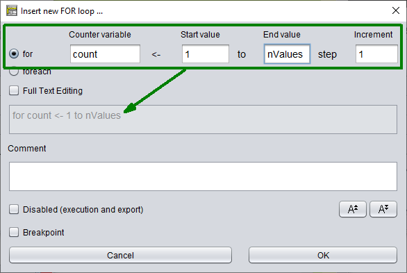
b) If you select the lower one of the two radio buttons (labelled "foreach" here), you will be presented the form for a traversing loop instead (see screenshot below). Again, you will have to specify the name of the loop variable but then a list of values, preferably comma-separated and within curly braces. But it might also be the name of an array variable or just a space-separated enumeration of some values. The listed values are not required to be numbers, not even literals. As before, the editor will immediately compose and present the control phrase.
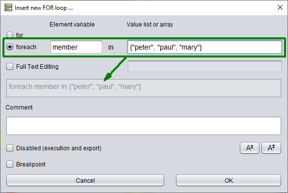
c) By selecting the "Full Text Editing" checkbox, however, the editor-internal synchronisation changes direction, i.e. now the text area (marked by a green box in the image below) will be enabled whereas the radio buttons and the form fields in the upper region simply show the conclusions Structorizer derives from parsing the control phrase you are writing. The parsing success depends on the keywords configured in Parser Preferences for counting (FOR) and traversing (FOR-IN) loops. The structured text fields in the upper region will immediately be synchronised whenever you touch the text. Be aware that the form fields may show some strange things while your control phrase is incomplete, incongruent, or ambiguous.
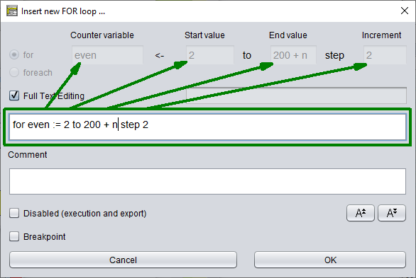
d) As soon as the entered text rather resembles the control phrase of a traversing loop (i.e. a FOR-IN loop), the radio buttons will switch and the upper part of the editor will change its appearance, i.e. the set of form fields including the labels will alter as the next screenshot demonstrates.
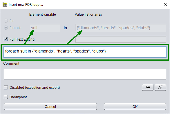
Synchronisation between the upper text fields and the larger text area starts as soon as you click into one of the active fields or toggle the "Full Text Editing" checkbox.
4. Fill in some helpful description in the comment area if you like — this will be the loop comment, obviously. Then commit the data by clicking the "OK" button or pressing key combination <Shift><Enter>.
5. Add instructions to the body of your loop. Therefore first select the empty element and then select an arbitrary type of element to insert it.
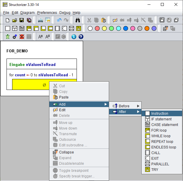
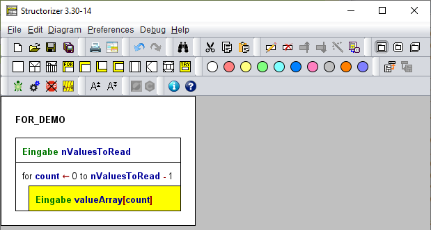
6. If you want to add instructions after the loop (instead of to the loop body) then first select the upper or left outer part of the loop element:
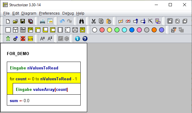
Now, this might be the complete diagram to compute the average (or mean value) of the numbers inserted to the valueArray, the two similar FOR loops are coloured light-blue:
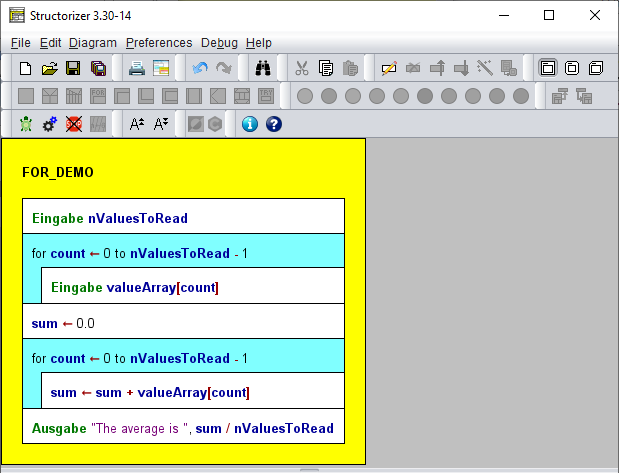
Note:
- Start and end value may be arbitrary expressions (though they should compute to integer values), whereas the step width (i.e. the increment) must always be an integer literal, otherwise it wouldn't be a predictable counting and you should use a WHILE loop instead. (Hint: you may easily transmute a FOR loop of counting type into an equivalent WHILE loop construct.)
- The Executor will reject any attempt to manipulate the loop variable within the loop body as illegal interference with the loop control mechanism (from version 3.25-10 on; before it just didn't have an impact on the loop control). Also see Analyser Preferences.
Download Demo.
Relation between Preferences and Editor
The image below explains where the different labels and settings come from. The keywords and strings in the green boxes (also the "foreach" label) are fed from the Parser Preferences and control the detection of the FOR loop parameters within the control phrase (loop header). So they may look different with other settings! The blue-boxed text in the full text area is the default text configured in the Structure Preferences. This will already have been filled in here when you add a new FOR loop and it decides which set of form fields is presented. If your default control phrase is that of a traversing loop then the lower radio button with its corresponding form fields will be active on opening the editor. If your default phrase cannot not be classified (because it is neither compatible with the parser preferences of a counting loop nor with those of a traversing loop) then the result is undefined and the form fields are likely to show some strange tokens.
Remark: The assignment symbol displayed between the "Counter variable" field and the "Start value" will always be "<-", but on composing the control text line from the upper text fields the assignment symbol appearing in the text area might be ":=" instead if the default FOR loop content configured in the Structure Preferences represents a counting loop using the ":=" operator. (Both "<-" or ":=" are accepted as assignment operators by Structorizer — whereas a simple "=" won't.)
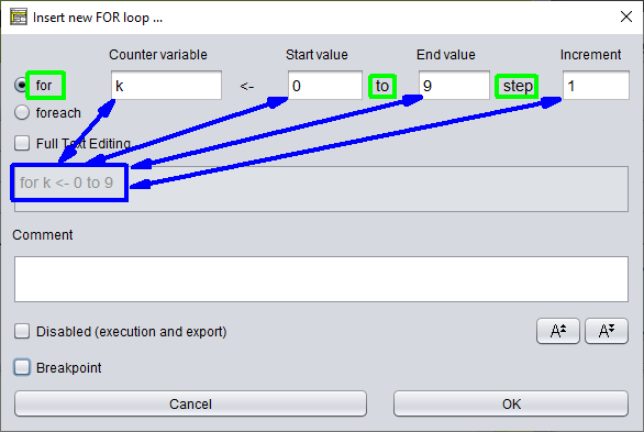
Error Messages and Hints
The editor has a non-editable field where it may display some message if you happen to enter e.g. a non-integral value (or an expression) for the increment in full text mode, or if it detects some syntactically defective value list in case of a traversing loop. See the screenshots below for an example.
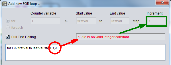
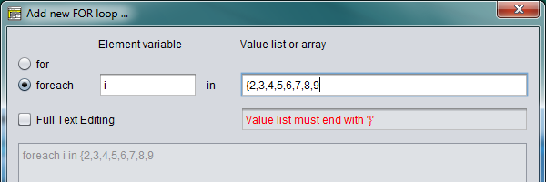
If you switch the loop style between counting and traversing loop via the radio buttons then in most cases the loop parameters filled in so far won't make sense anymore and will have to be discarded. To protect you against inadvertent data loss, the editor will raise a warning dialog allowing you to back off (cancel the change):
On changing from a counting loop with only constant parameters, however, the editor would convert it to an equivalent traversing loop, if the number of elements doesn't exceed a reasonable limit (currently 25). The example shows such a counting loop before altering the loop style...:
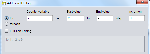
... and thereafter:
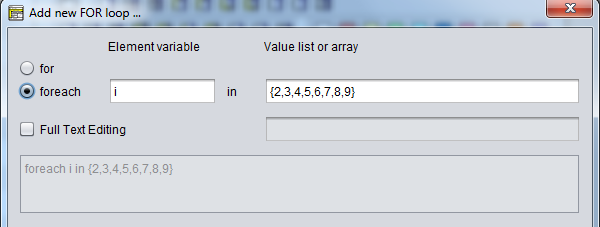
The conversion above is not reversible, i.e. the editor won't bother to find out whether a value sequence is a continuously enumerable integer interval. Actually, in most cases such a conversion would not be possible.
If you edit an existing FOR loop then the editor will automatically detect the style of your loop and present the parameters in the form fields. If the editor opens with "Full Text Editing" mode being active, however, then some discrepancy among the stored control phrase and a phrase generically composed from the contents of the form fields was detected.
Further Examples and Syntactic Possibilities
In the diagram below you see a counting loop and several traversing loops (configured with keyword foreach here), even nested ones (green).
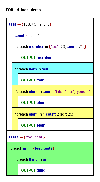
As you may see, in addition to array variables and array initialisation lists, mere item enumerations (separated by comma or even blanks) are also accepted (yellow loops).
Obviously, a list consisting by design of a single atomic element, as in e.g.
foreach elem in 23
doesn't make much sense since no loop would be required to apply the loop body (not shown here) just once to this only value. Therefore it is syntactically not supported.
If the list consists of a single string, however, then the loop body will be executed for every character of the string (since release 3.27):
foreach c in "This string will be split"
If the collection part consists of a single variable, as in
foreach elem in some_variable
then the variable is required to be an array or string variable and will be handled this way. If there are two or more variables, in contrast, then they will be treated as elements, i.e. as if they were enclosed in braces (like in the outer one of the green loops).
Hint: You may decompose a counting FOR loop into an equivalent sequence of an initialisation instruction and a WHILE loop, simply by means of the transmutation wand  .
.
4.6. WHILE loop
A WHILE loop repeatedly executes a sequence of instructions — called its body — while a given Boolean condition holds. The logical condition is an entry condition i.e. it is tested each time before the body is going to be executed. If the condition expression is false on entering the loop element (the first time) then the loop body will not be executed at all.
The text to be filled in on adding a WHILE element is a Boolean expression, i.e. the logical condition. This may be a comparison, a variable with Boolean content, or several conditions combined by logical operators (see more details under IF statement). Please note:
The default text can be modified under Preferences › Structures.
This is how you add a WHILE loop to your diagram:
1. Click on the WHILE loop symbol in the toolbar (having selected the element, after which the WHILE loop is to be inserted):
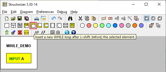
2. Write a condition (a Boolean expression) into the text field:
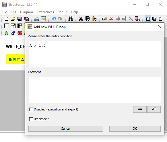
3. Add instructions (i.e. the actions to be repeated while the condition is being true — it may of course also be elements of any other kind) into the loop body:
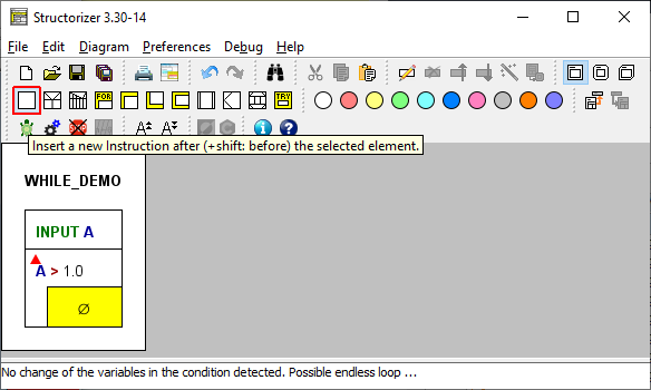
(The little red triangle in the loop element as shown above is just to draw your attention to a related Analyser warning in the Report list at the bottom. By the way, this warning is an important observation: Once you enter the loop, you will not ever have a chance to get out of it if the body does not contain an instruction with a possible impact on the condition, i.e., if none of the variables in the condition gets modified by an instruction within the loop body then you are caught forever! So you will see this warning with any new loop since its body is initially empty.)
4. If you want more than one instruction executed then just add them after or before the first one:
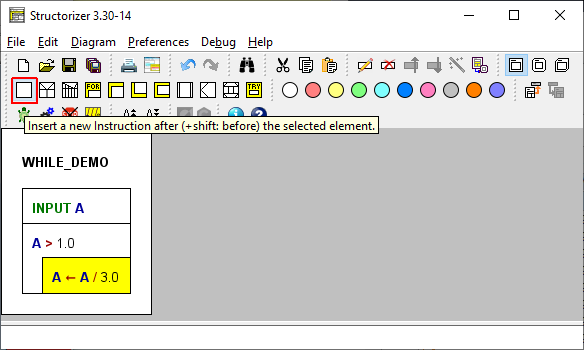
5. If you want to add further instructions after the entire WHILE-Loop then you must select the loop head first:
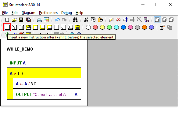
6. This is what the finished version looks like:
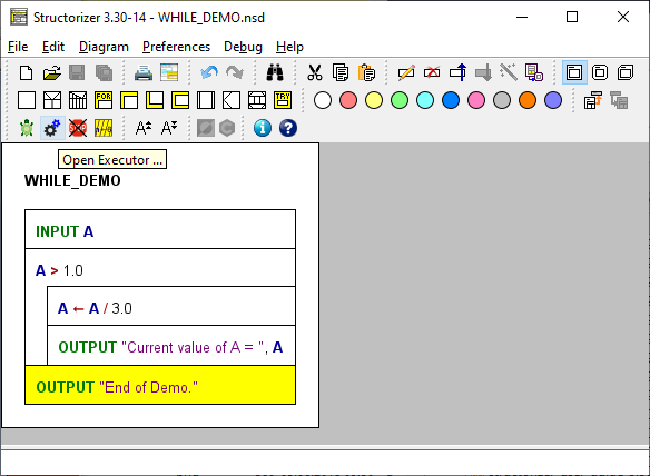
Download this Demo
Download other Demo (Newton's square root)
4.7. REPEAT loop
The text of a loop element of type "REPEAT UNTIL" is supposed to contain a Boolean expression (a logical statement) representing the exit condition of the loop.
A REPEAT loop will repeatedly execute a sequence of instructions — called its body — until the exit condition becomes true. If the condition evaluates to false when entering the loop element then the loop body will still be executed at least once.
Please note:
The default text can be modified under Preferences › Structures.
This is how you add a REPEAT loop to your diagram:
1. Select the element where you want to insert the REPEAT loop, then click on the REPEAT loop button in the toolbar (or select the respective menu item in the context menu or Diagram menu):
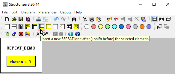
2. Insert a Boolean expression as exit condition:
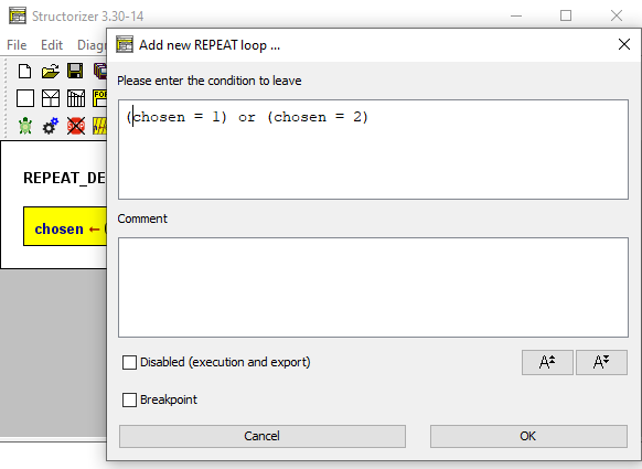
3. Add instructions (or any other elements) to the loop body:
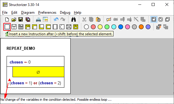
(Note the little red triangle in the loop element, which indicates that there is a related Analyser complaint in the bottom report list. These markers were introduced with version 3.30-14. The Analyser warning — and with it the red flag — will be gone as soon as the intended INPUT instruction for variable chosen will have been inserted. For a short discussion also see the WHILE page.)
4. If you want more than one instruction executed as body then simply add the extra elements after or before the first one.
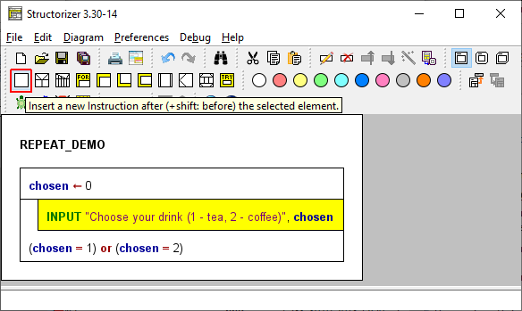
We want to insert an additional instruction before the selected INPUT element, so we will keep the <Shift> key pressed while we click on the respective element button in the toolbar...
5. If you want to add further instructions after (or before) the entire REPEAT loop then you must first select the loop foot:
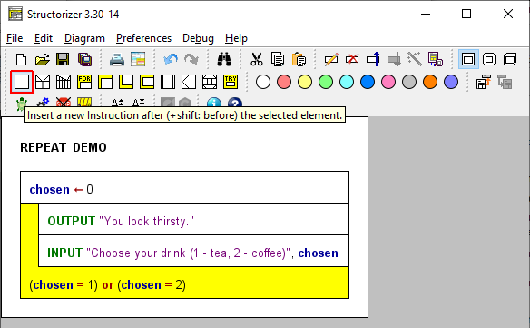
6. This is what the finished (and already saved) version looks like, now:
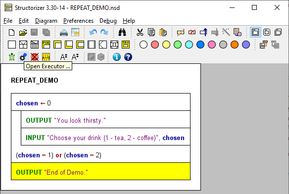
You might test or debug it with the Executor now or export it as code etc.
Download Demo
4.8. ENDLESS loop
An ENDLESS loop infinitely repeats the loop body — without a condition to enter or exit.
Hence an endless loop itself does not contain any text. The text entry area in the editor is disabled therefore.
You may, of course, add comments.
Endless loops in a way contradict the concept of an algorithm as an effective computation description that proceeds through a finite number of steps. (Endless loops are typically rather an unfamous programming mistake with WHILE or REPEAT loops when the loop body has inadvertently no impact on the loop condition.) Yet explicit endess loops may be useful e.g. in a context of machinery control. In order to make sense, an endless loop requires the loop body to be computable in finite time, of course.
By means of an EXIT (Jump) instruction you could possibly break out of an endless loop, but if there are predictable circumstances instigating a leave, then it will always be preferrable to use a conditional loop instead.
This is how you may add an ENDLESS loop to your diagram:
1. Having selected the element before or after which you want to add an ENDLESS loop, press e.g. the respective toolbox button (or press the <Ctrl><F7> key combination, with versions ≥ 3.29-13):
2. Fill in some comment if you like (the upper text field is disabled).
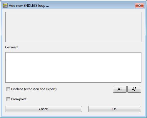
3. Add instructions (or structured elements) to the body (cf. e.g. WHILE loop)
This might result in e.g. the following diagram (making little sense, of course):
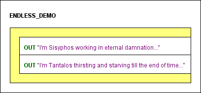
A maybe more sensible but very abstract example of an endless control loop might be:
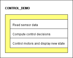
Except for the capacity of digital input/output, the control loop might even get more plausible by delegating tasks to subroutines:
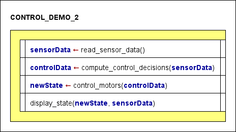
4.9. CALL
Subroutine CALLs
The CALL element is quite similar to a simple instruction. The difference is that the executed instruction is the invocation of a user-defined subroutine (also see Type) represented by another diagram, i.e. the execution control is delegated to that other diagram, which then (after having done its job) returns control hitherto where it gets passed to the next element..
Subroutines may be classified into procedures, which do not return a result and are used as command, and functions, which return a value and are to be used as expression. Hence, the calls to procedures and functions differ slightly in their syntax. Generally, in a programming language, functions could be called at arbitrary nesting levels in expressions (as is possible with the built-in functions of Structorizer). With the CALL elements in Structorizer referring to other (customer-defined) diagrams it's different, however:
If you want to allow the Executor to perform such a CALL element or if you want the code export working then the CALL should contain just a single line, either of the form
procedureName(value1, value2, ..., valueN)
or
variable <- functionName(value1, value2, ..., valueN)
The argument list may be empty, but the parentheses must not be omitted. The arguments (value1 through valueN in the templates above) may not only be represented by literals or variable names but by arbitrary valid expressions with operators and built-in functions. The only restriction is that the expressions may not contain further custom-routine CALLs. The argument expressions are to be separated with commas.
A call must provide as many argument values as the called routine has parameter names in its header. They are mapped one by one in the order of the parameter list. If there are overloaded subroutines (i.e. several subroutines with same name but different numbers of parameters) then the argument number of the call decides which of the routines gets invoked.
Since version 3.29-05, subroutines may have optional parameters at the end of the parameter list. In this case, the call may omit as many argument values (from right to left) as parameters in the routine header are equipped with default values. These default values will be used instead of the omitted arguments. If an argument is given then the default value will no be used.
Version 3.32-11 introduced an autocompletion mechanism in the element editor that offers the signatures of all matching subroutine diagrams that are held in Arranger at the moment of editing. Its further functionality is described on page Content Assist.
Example
Here is a simple example of a CALL element (yellow) within a function diagram:
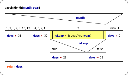
The called function is defined by another diagram (see Executor guide and Arranger page to learn how calls can be executed in Structorizer):
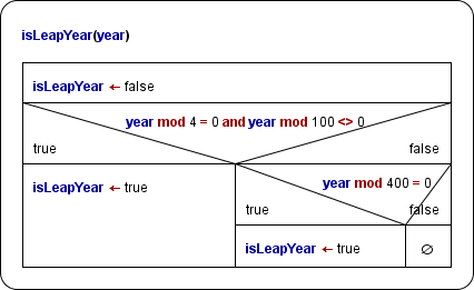
The calling two-parameter function diagram daysInMonth above is of course also meant to be called by another algorithm.
On the Runtime Analysis manual page you will find an example of a pretty complex bunch of routines co-operating in the task of sorting an array; the core algorithm there (quickSortRecursive) is a recursion example.
Recursion
If you want to write a recursive algorithm, you ought to place the recursive call into a CALL element as described above. Example:
|
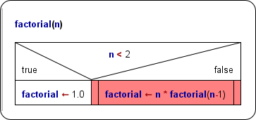
|
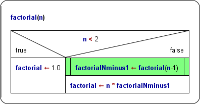 |
Though this diagram shows a fundamentally correct recursion,
it will not be executable in Structorizer because the CALL element (red) does not only consist of target variable, assignment symbol, and function invokation but embeds the function call in a multiplication. |
This version of a recursive factorial algorithm decomposes the recursive branch into the assignment with the pure call on the right-hand side and a separate multiplication instruction. This way, Structorizer can execute it. (The expression n-1 as function argument is no problem.) |
Instruction transmutation, routine outsourcing and editing
There are some very helpful features to facilitate the creation of CALL elements or their corresponding subroutine diagrams.
- If you happened to write a subroutine call into a simple Instruction element by mistake, then you don't need to delete the element, to insert a Call element and to enter the entire statement text again. Instead, by clicking the magic wand button
 (with the Instruction element selected) you may transmute it into a Call element (with same content). This can also serve as an easy test whether the statement complies with the syntax rules stated above. (Otherwise the transmutation button simply won't work.)
- If you realize that a designed algorithm has grown too large and should better be decomposed then you may "outsource" parts of the diagram into subroutine diagrams. Simply select the logically consistent element subsequence you want to make a subroutine from and click the menu item "
 Outsource". This will move the selected elements to a new subroutine and fill the gap with a Call to that subroutine diagram. See Outsourcing for details.
- You may summon the called routine for editing or inspection (since version 3.29-04). Another Structorizer instance, related via Arranger, would open to show the summoned routine. There are respective items in both the "Edit" menu and the context menu:
If the referenced routine cannot be retrieved from Arranger, then you will be asked whether you want to create a new subroutine diagram for the referred signature:
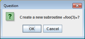
You may decline here, or continue, in which case Structorizer will set up a new empty diagram with a routine header vaguely inferred from the call, ready for editing:
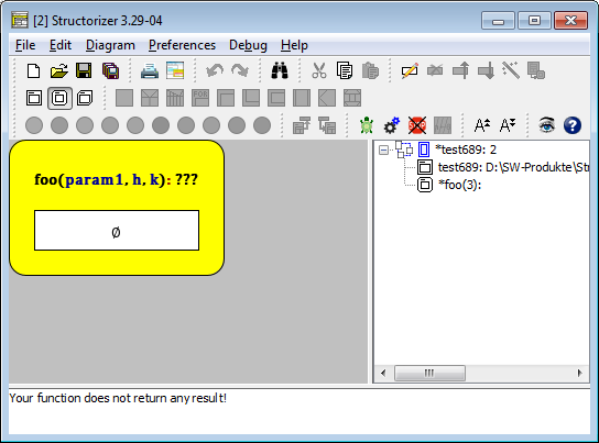
As you can see, the new routine diagram will automatically be added to the group of the parent diagram, possibly a new group may have been generated for this relation.
Method declaration reference
Diagrams resulting by source code import from an object-oriented language like Java or Processing (since Structorizer release 3.31) may contain special CALL elements that were deliberately misapplied as mere method reference declarations — they will permanently be disabled (see the green elements with hatched side-bars at the end of the diagram shown below) but allow to summon the related diagram into an additional Structorizer window via the menu item "Edit Sub-routine ..." in either the "Edit" or the context menu or via key binding <Ctrl><Enter>:
(The above diagram is a
source code import result - be aware that
new operators are not supported by the
Executor und will be marked as "uninitialized variable" by the
Analyser.)
On COBOL import, the same misapplication is used to place unsatisfied section or paragraph labels from the source code, in a way that they can't cause harm, into the diagrams at the corresponding places:
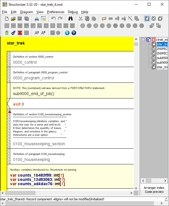
A special benefit of these misapplied CALL elements is that series of them (together with neighbouring genuine declarations) can be collapsed with the display mode Hide mere declarations:
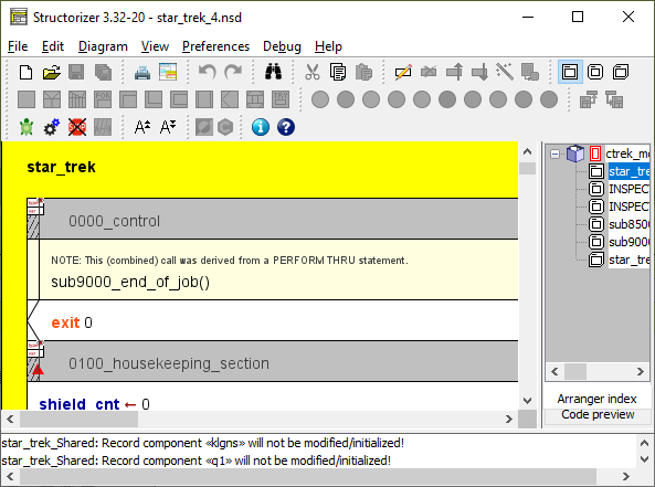
In contrast to the method declaration reference elements as used for Java, Processoing, and Delphi import, for the CALLs misapplied as COBOL label markers, the "Edit Sub-routine ..." action is not enabled.
Note that such specifically diverted CALL elements cannot be inserted or generated manually, they will only occur as product of source code import. Since version 3.32-20 they differ visually from disabled ordinary CALL elements by their hatching: whereas disabled ordinary CALL elements are completely hatched, the hatching on these method / label reference elements is restricted to the side bars (which also helps legibility of the element text and comment).
4.10. Jump (EXIT)
The Jump (or EXIT) element indicates some kind of explicit exit from a loop, a routine, or the program. It is not actually a means of structured programming, it rather contradicts the ideas of this concept. It can always be avoided (see example below), but may sometimes be a pragmatic and convenient way to formulate algorithms that otherwise would require some complicated workaround with logical variables, additional conditions etc.
Version 3.29-07/-08 introduced a fourth flavour of Jump element: The throw instruction (aka raise instruction). It is used to leave the current algorithmic context in case of a detected problem (an exception) that can not be solved on the current level but might be handled by some higher context with a more general perspective if we pass the necessary information there. If the thrown problem can be solved on a higher level then the execution may be continued on that level, otherwise the program will abort (as if we had used an exit command). This use of an EXIT element is possibly the most justifiable one.
You are not encouraged to use Jump elements, however.
The following types of "jumps" are supported both on execution and code export:
- Loop exit: an empty Jump element or a Jump element containing simply the keyword
leave
will just prematurely leave the closest surrounding loop, no matter of what kind. (This form is roughly equivalent to the break statement in languages like C, Java etc.) If the Jump element is contained by several nested loops, then an instruction
leave n
(n being a positive integer) within the Jump element will exit from the innermost n loops, such that execution continues with the next instruction after the outer one of the left loops.
Remark: leave 1 is equivalent to leave or an empty Jump element.
- Routine exit: To leave a routine (the current diagram) immediately, write
return
into the Jump element. This can also be used to return a result value. So if the routine is to provide a result then just write an expression describing the result value or its computation after the keyword return, e.g.
return a * (b + 3).
- Program exit: The keyword exit allows you immediately to terminate the entire program, even from within a subroutine. An integer value is expected to be appended as exit code (by default 0 would be passed), e.g.
exit 17
- Raising of an exception: Since version 3.29-08, an experimental enhancement allows you to model a kind of simplified structured exception handling. In combination with TRY elements you may raise (or throw) a string as exception (error message) that can be caught by the catch section of a dynamically encapsulating TRY element. In order to launch an error you my write e.g.:
throw "Problem with file " + filename
Note: Since release 3.29, the pre-configured keywords mentioned above (leave, return, exit, throw) are subject to customization, see Parser Preferences, e.g.:
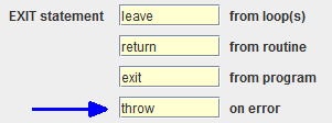
Since version 3.32-11, the text area of the element editor provides an autocompletion mechanism that facilitates the typing of the above configured keywords at the beginning of the element text line and also suggests the matching names of used variables after a small number of typed identifier characters after the keyword. See page Content Assist for further details.
Example for a conditioned Jump used to leave a FOR loop prematurely:
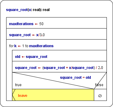
Of course the Jump could easily be avoided by decomposing the FOR loop into a WHILE loop (green and yellow elements) using both the negated condition of the Alternative and the maxIterations limit as (re-)entry condition (see Transmutation for an automatic FOR loop decomposition):
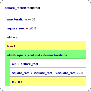
Instruction transmutation
If you happened to write a Jump statement of one of the supported kinds into a simple Instruction element by mistake, then you don't need to delete the element, insert an EXIT element and enter the entire statement again. By clicking the magic wand button  (with the erroneous Instruction element selected) you may transmute it into an EXIT element (with same content). This can also serve as an easy test whether the statement complies with the syntax rules stated above. (Otherwise the transmutation button simply won't work.)
4.11. PARALLEL
What is a Parallel section?
The Parallel element is to represent a bunch of concurrent threads that are started at entering the Parallel element and waited for at the end of the Parallel element, i.e. the Parallel element is not left before all launched threads have terminated their respective algorithms. This way, the Parallel section contains a synchronisation.
How should a Parallel section be formed?
Whereas you may insert arbitrary instructions in the parallel branches, the usual practise is to represent the threads by subroutine calls. Some programming languages (and the StrukTeX export) even expect the threads (branches) to be calls of thread functions of a certain signature. This makes sense since otherwise there would be a high risk of mutual impacts on common variables, leading to races, hazards and inconsistent results. (If the respective Analyser option is activated, you will get warnings on some obvious potential inconsistencies.)
Code export
Currently, for many of the code export languages there is a strategy to convert Parallel elements into working multithreading code, e.g. C++, C#, Java, Python, Perl, and bash/ksh. Usually, first worker classes or function objects are defined from the branches of the Parallel element, then for each of them a respective thread will be started, and after their termination has been awaited, variable values assigned inside the threads will be extracted from them for further use in the main thread. For target languages not supporting multithrading (e.g. for C there is no system-independent thread support in the standard libraries) or without accomplished generator support, the code export just serializes the branches of the Parallel elements but marks them with eye-catching comments, such that the user might try herself to find a concurrent solution.
Execution / Debugging
By the way, the Executor will not actually be able to run the threads in parallel. Instead, it will try to simulate concurrency by randomly choosing due instructions from the pool of still unterminated threads, but this will not go deeper than just the first instruction sequence level. Hence, loops, calls etc. will always be executed completely in sequential mode before the thread has to yield control to another waiting one.
How do you add a Parallel element, now?
1. Select the element before or after which you want to insert a Parallel element.
2. Click the respective item in the context menu or the toolbar button marked red in the image (while optionally holding down the <Shift> key) or press the <F13> key if available (versions ≤ 3.29-12) or the <Ctrl><F6> key combination (versions ≥ 3.29-13).
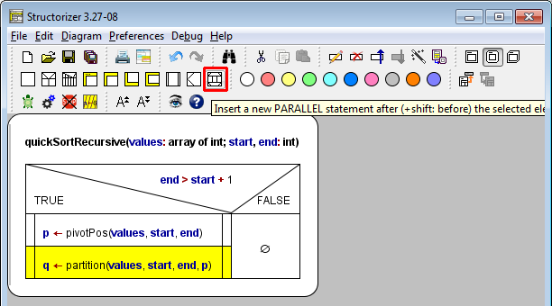
3. When the Element editor opens, just write the number of parallel threads into the text field, no more, no less. Only a constant cardinal number will work here. For any kind of explaining text, use the Comment text area.
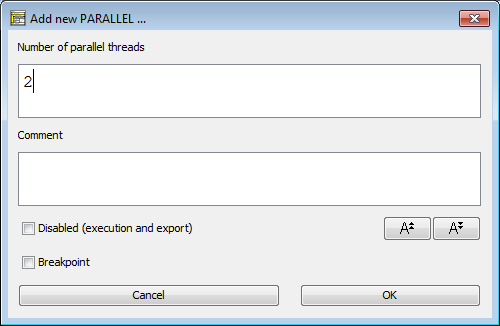
If you edit an existing Parallel element then be aware that on reducing the number of branches the superfluous extra threads will automatically be removed. (So if you want to keep a backup of them, do it before. But you may of course undo the thread number reduction and hence the removal in case you had forgotten to stash the thread contents.)
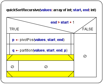
4. Insert elements to the branches as usual — each branch behaves as an ordinary instruction sequence -, but keep the introductory remarks in mind: It is preferrable to let the threads be single subroutine calls each, like in the following recursive-parallel implementation of a QuickSort algorithm (for easier recognition, the two concurrent threads were dyed differently):
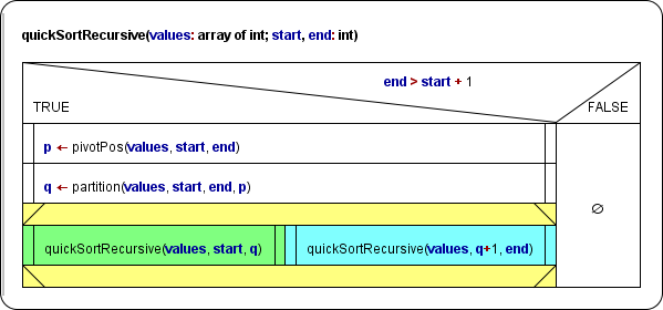
The execution order of the green and the cyan calls will be randomly chosen.
4.12. TRY block
A TRY element (versions ≥ 3.29-07) is a non-standard element in a structogram, expressing structured exeption handling (aka error handling), which is an advanced concept for experienced programmers. Therefore TRY elements are not available in Simplified toolbars mode. If you are not familiar with structured exception handling you might read the background explanation first.
The TRY element is not among the official set of elements proposed by Isaac Nassi and Ben Shneiderman nor has it been included in the DIN 66261 standard (it simply hadn't been "invented" back then), but is integrating surprisingly well in the element zoo. (The implementation in Structorizer, available since version 3.29-07, is of experimental character.)
How do you insert and use a TRY element in Structorizer?
Imagine the following scenario: You want to write a routine that opens a file with given name and tries to read an integral number from it. Several things might go wrong: The file might not exist, not at least in the current directory, or the content might not be readable as number. The routine itself won't have an idea, from where and for what purpose it was called, so it can only detect an occurring problem but not propose sensible workarounds. It will have to leave it to the caller. The caller, however, must get an information about the nature of the problem in order to handle it. The routine might look as follows (see File I/O API, also for other examples making use of TRY blocks):
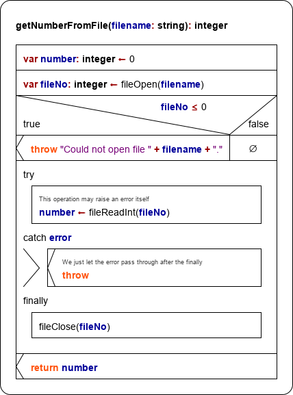
The result will be put to variable number. Therefore it is declared and initialized at top. Then the routine tries to open the file. The built-in function fileOpen will not raise an error but return a value equal to or less than 0 if the opening fails. So in this case our routine will raise an exception itself with some meaningful text. A throw Jump exits from the routine by stack unwinding (see background explanation). In the other case our routine attempts to read an integer via fileReadInt. This function will cause an error in case the file is empty or the initial part of the contained text in the file cannot be converted into an integral number. This would be okay, but we don't want to leave the file open. Therefore we put the error-prone instruction into a TRY block such that we can force the closing of the file in the finally section. The TRY element will catch (and thus neutralize) the error, though, no matter whether the catch section does anything or not — the error would be regarded as caught and handled. The routine would end regularly. But we don't want to let the error go unnoticed (though the caller might possibly conclude from the unchanged result value 0 that something must have gone wrong). So we decide to rethrow the caught error. This is done by simply inserting an empty throw Jump into the catch section. The effect of the rethrowing will be postponed until the finally section gets accomplished.
Now let's construct this routine in Structorizer.
First of all: You must have switched off the Simplified toolbars mode (menu "Preferences › Simplified toolbars?"): TRY blocks are only available in standard GUI mode.
1. Select the element before or after which you want to insert the TRY element:
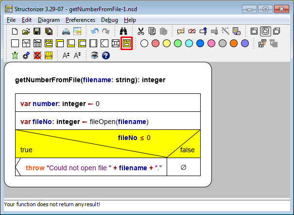
2. Select the TRY icon in the toolbar (holding the Shift key down if you want to insert the TRY block above the selected element) or add it via the respective menu item "Diagram › Add › Before/After › TRY" (or via the context menu). Akternatively you may also press the <Ctrl><F5> key combination (versions ≥ 3.29-13). The element editor will pop up (see screenshot below). Now please resist the temptation to write the protected instructions here! Instead fill in just a name (or entire declaration) for the exception variable. This variable will hold the exception string thrown by the failing code (or by the Executor itself) such that you can work with it in the catch section. Again: DON'T write the protected code here (this will be done in the next step)!
You won't do wrong, however, to write some useful comment in the comment field.
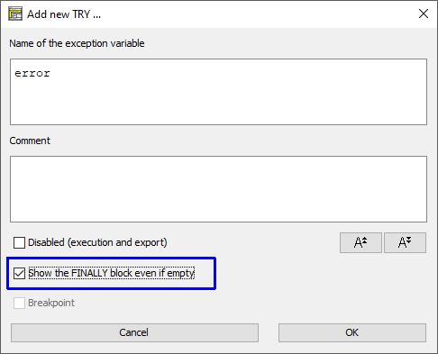
Note the checkbox "Show the FINALLY block even if empty" marked with the blue box in the screenshot above. It was introduced with version 3.30-15. If it is not checked then the created TRY element will not show a finally block, such that we could not add elements to it. Our plan, however, is to ensure the file gets closed no matter whether an error occurs or not. So we will need the finally section (see step 5 below), hence make sure to have the box checked. No problem if you forgot it: you may still check it any time later, whenever you open the editor for the TRY element again. Before version 3.30-15, the finally section was always drawn, which unnecessarily consumed space for empty finally sections.
3. The inserted TRY element looks as shown in the following screenshot. Now it gets time to put instructions or arbitrary elements in the protected upper section (between the labels "try" and "catch". You do so by selecting the field with the empty set symbol and inserting the elements you like as described in the respective sections of this guide:
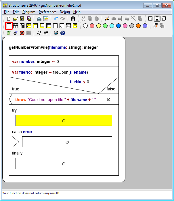
4. Now select the central block of the TRY element to specify the error handling activities. This part will typically make use of the declared exception variable to find out what's the matter and possily to output the content to the user. Just insert the elements you need in the usual way. In our example we want to rethrow the exception, so we will insert an EXIT element:
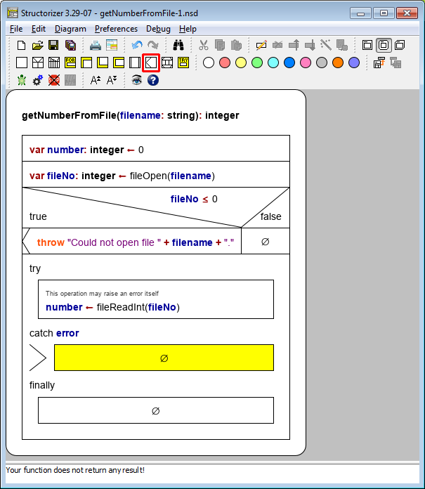
The Jump element is to be filled with the keyword configured in the Parser Preferences for the EXIT statement on error:

5. The lower block in a TRY element is reserved for the "cleanup" activities. These are guaranteed to be carried out, no matter what happened in the try and the catch sections. This section may be empty if no cleanup is necessary. In our example, we want to make sure that the obtained file resource is released to the operating system, so we add a fileClose instruction:
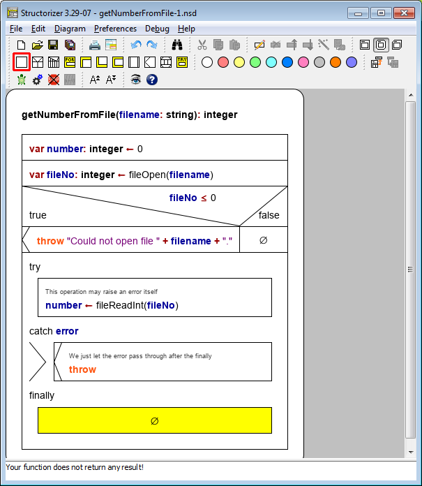
6. After having filled the entire TRY element we may go on adding elements to the routine. So just select the TRY element as a whole (clicking on its outer frame) and append the return instruction for the routine:
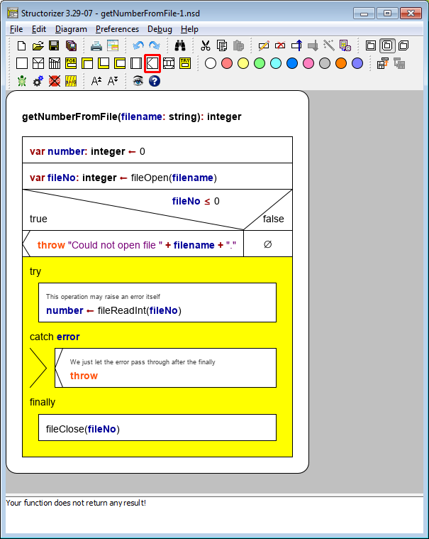
7. Now the routine is ready and can be pushed to the Arranger (which is serving as subroutine pool for the Executor).
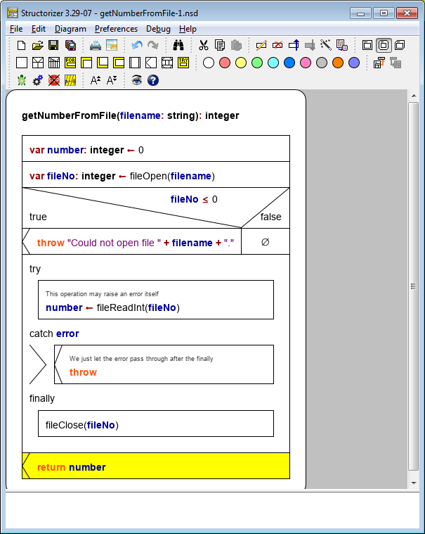
7. We might now create a main diagram, making use of the above routine. Let's assume we want to retrieve a million Euro from the account of the user and ask him to tell us the name of a file where the account number is stored (assuming that it is a plain number, not an IBAN string). Now we can use our routine getNumberFromFile just built, but we know it may throw errors, so we better prepare. Sensibly, we will call it in a TRY element. This time, a finally section isn't needed, since there is no resource we introduce on the main level (the file is already cared for by the routine itself). In the handling section we just tell the user, what error text we obtained — it will be in the variable specified in the TRY element editor, here we named it exception. Then the user is asked to choose another file:
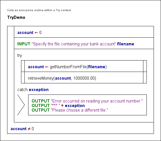
This is of course a very unsophisticated algorithm, not even offering the user an escape. So it is open for your improvements. (And we don't show you how to retrieve money with a Structorizer routine, of course  . You ought to create a dummy routine retrieveMoney(2), see CALL elements how to derive a routine diagram from a CALL.)
You may check this little program in Executor to watch how the mechanism works. The Arrangement archive may be downloaded here:
TryDemo.arrz
Here is a more simple example (the finally section was left empty, so since version 3.30-15 it will not show by default):
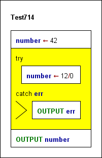
Background explanation:
When Nassi and Shneiderman proposed their modelling approach for structured programming around 1973, the concept of structured exception handling (SEH) hadn't been coined yet. So it is no surprise that the set of Nassi-Shneiderman diagram elements (according to DIN 66261, in particular) does not contain elements for structured exception handling. Most modern languages, however, provide specific syntactic structures to support error handling in a safe and convenient way, typically in form of try-catch blocks, complemented by a means to raise ("throw") a problem up to the level that can handle it. If not being excessively abused, structured exception handling is a powerful programming technique that avoids the recursive passing of status values as routine results possibly several call levels up, which requires repeated checking and gets in the way of ordinary result propagation.
Programmers frequently face a problem, often related to external resources (e.g. a file that cannot be opened or has unsuited content), that could be solved (or worked around) but not sensibly on the current level within nested loops or in a deep call situation. The solution may require user interaction or at least some larger overview at a higher level where more knowledge about the context and aims is available. So the information about the problem is to be passed to that higher competence level, usually several call levels up. To do this via the ordinary subroutine parameter lists or return values is possible but pollutes the call interfaces (routine signatures) along the path with lots of sporadically needed pecularities. To do this out of a deeply nested algorithm structure may be even harder.
The central idea is now to provide a protected environment — the "Try" block — where operation sequences being prone to fail at some low-level detail can be put into. This instruction sequence is guarded by some error handling code — the "Catch" block — that goes into action if one of the expected potential problems (exceptions) actually occurs. To this purpose, the code part immediately facing the error (e.g. a low-level subroutine) simply "throws" the error information up in the hope that it might be "caught" and handled by the lurking catcher of the "Try" environment. If it wasn't in such Try context then the thrown error will rise up to the top program level and make it crash.
"Try" structures may be nested. Hence, if the catcher of a "Try" block decides not to be competent enough to handle the exception it may "rethrow" it, such that it might be caught by some outer "Try" block guard. Again, if no "Catch" block along the stack path up handles the problem then the program will get killed.
The raising of the exception goes along with "stack unwinding", i.e. the call contexts being left are removed from the stack as if they had returned, though they are not of course continued, the remaining operations of the unwound levels are simply abandoned.
On the catching level, however, there is the helpful possibility to specify a "Finally" block that is executed either way, no matter whether the tried instructions succeeded or caused an exception, and no matter whether the exception was caught and handled or rethrown (passed further up). This Finally block is intended for necessary cleanup activities, i.e. to dismiss ressources acquired within or immediately before the Try block. Its execution is guaranteed unless it causes an error itself. But if an exception occurred and was not handled or rethrown then stack unwinding and raising of the exception will inevitably go on after the Finally block is finished. The instructions following the Finally block will only be executed either if no exception occurred or if the occurred exception had been handled by the "Catch" block.
5. Diagram
The editing of Nassi-Shneiderman diagrams can be done via menus, mouse actions, and keyboard actions. It follows usual conventions and is therefore practically self-explaining.
The affectable units of a diagram are the elements (i.e. the basic structures of any algorithm). Generally, elements may be selected by mouseclicks. Having selected an element, the selection focus may be moved around by pressing cursor keys (up, down, left, right) in an intuitive way (see yellow arrows in the image below). The vertical traversal path is closed to a ring, i.e. if you go downwards from an element positioned at the bottom of the diagram (there are six of them in the image below though logically the big IF statement as a whole is the last element of the diagram), then the selection will leap to the top element of the diagram etc. On going upwards or sidewards, the selection will always be fetched by the central adjacent element in the target direction if there are several of them. If substructure elements of an adjacent structured element are closer or as close as the selectable part of this then you will dive into the substructure first.
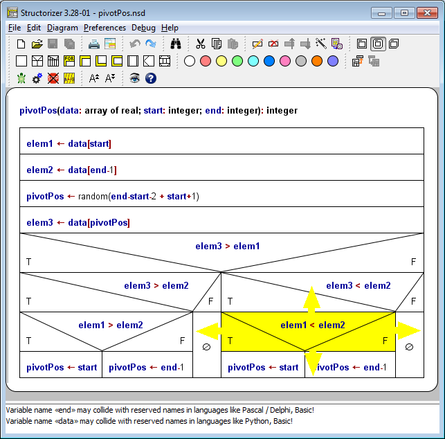
In order to extend a selection within the same block (meaning a vertical sequence of consecutive elements), you may press <Shift><Up> or <Shift><Down> key to include the next element above or below, thus forming a selected subsequence of the current block (see the green arrows in the image below). Alternatively, you may — with <Shift> key pressed — click on the element at the other end of the intended selection span. There is no possibility to add an element to the selection that is not a direct member of the same block. (Until version 3.30-08, the selection span could only be expanded but not be reduced. When the span had accidently been expanded too far, one had to start again by selecting the element at one end of the wanted span and extending the selection in the way described.) Since version 3.30-09, the selection span can be reduced the same way (e.g. by clicking closer to the initially selected element or pressing the opposite one of the key bindings <Shift><Up> or <Shift><Down>). Key bindings <Alt><Shift><Up> and <Alt><Shift><Down> alway add the next element at top or bottom of the current selection span to the selected subsequence.
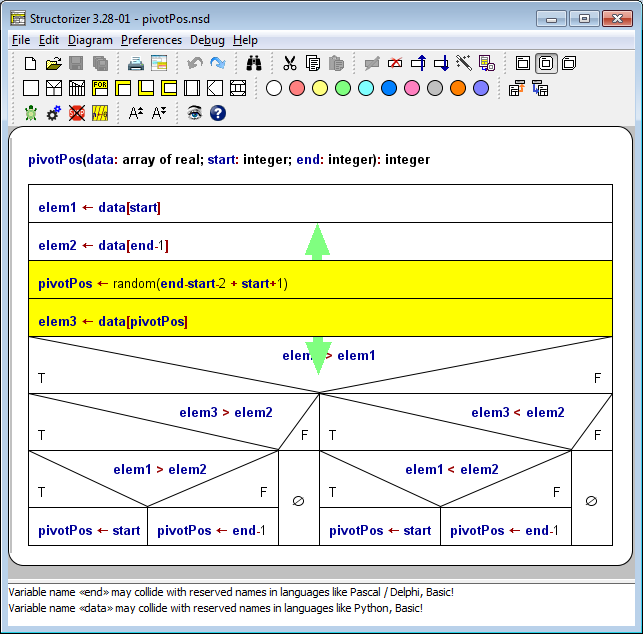
In order to extend the selection to the entire element sequence (block) the selected element is being part of, just do a mouse click with <Alt> key pressed (be aware that in many operating systems you may have to press the <Alt> key again to reset the <Alt>-activated state afterwards).
By the way: Pressing the <Alt> key shows the mnemonics for the main menu by underlining the respective letter of the menu caption. (Press <Alt> plus the mnemonic letter to open the respective menu via keyboard, then you can navigate through the menu by cursor keys). Note that since version 3.24-10 the mnemonics may depend on the chosen language such that e.g. with English or French being the chosen language the File menu will open by pressing <Alt><F> ("File" / "Fichier") but no longer with German language chosen, where <Alt><D> ("Datei") is to be used instead. The mnemonics is not always the initial letter because in some languages several menu captions may start with the same initial letter. As it is locale-related, it has become subject to the locale configuration via the Translator tool (introduced with release 3.25).
Double-clicking an element oder pressing the <Enter> key opens the editor for the selected element.
Pressing the <Del> button removes the currently selected element(s).
Nearly all changes to elements and their order are undoable (by <Ctrl><Z>, Edit menu, or speed button  ) and redoable (by <Ctrl><Shift><Z>, by <Ctrl><Y>, Edit menu, or speed button
  ). The depth of the undo and redo stack is not formally limited. The undo stack is not cleared by saving the diagram, i.e. you may even undo changes already saved. You will notice when a sequence of undo/redo actions has reached the diagram state last saved again: The save button will then temporarily be disabled.
The subsections below give some detailed descriptions what operations can be applied to selected elements (or element sets). Also see section Key Bindings for a list of applicable key actions.
For algorithm-specific editing explanations, i.e. with respect to the different types of elements being insertable into a diagram, please consult the Elements section.
5.1. Type

Structograms in Structorizer can be divided into three categories:
- main programs (as in any sequential programming language),
- subroutines (procedures, functions, methods),
- includable diagrams (shared definitions, global initialization)
Main programs are drawn with square corners whereas subroutines are drawn with rounded corners. Includable diagrams are drawn with bevelled upper left and lower right corner. Depending on the chosen type of diagram and whether your diagram is boxed or not, the diagram is drawn differently.
You may alter the type of a diagram via the menu or by using the speed buttons: 
The following table resumes all cases by giving an example:
Note:
- The type of the diagram (main or sub) usually influences the source code generator and may thus result in different code.
- Only diagrams of type sub are callable, i.e. may be employed by the executor if referenced in a Call element (also see Program/Sub).
- Diagrams of type includable are meant to be referenced by a main, sub, or other includable diagram via the include list (see Program/Sub).
- As to be seen in the images above, the heading (and the possible bottom margin) of an un-framed diagram will appear in gray whereas the box of a boxed diagram is white (unless being selected or marked as test-covered, of course).
5.2. Add element
To add an element to the diagram, you proceed like this:
- Select an existing element or an empty block by clicking on it (or by traversing the selection via cursor keys to it).
- Then you will have four possibilities:
- Do a right click on the selected element and use the contextual menu "Add › Before" or "Add › After" to insert a new element before or after the selected one. Simply choose the needed kind of element from the submenu.
- Use the menu "Diagram › Add › Before" or "Diagram › Add › After" to insert a new element before or after the selected one. Simply choose the needed kind of element from the submenu.
- Use one of the speed buttons in the tool bar:
 .
.
If you hold the <Shift> key pressed when clicking on the chosen button then the element will be inserted before the selected item, otherwise after it.
- Use the respective function key shown in the according menu item of "Diagram › Add › Before" or "Diagram › Add › After" (e.g. <F6> to append an IF statement to the selected element, <Shift><F6> to insert an IF statement before the selected element etc.). On page Key bindings you'll find the complete list as well.
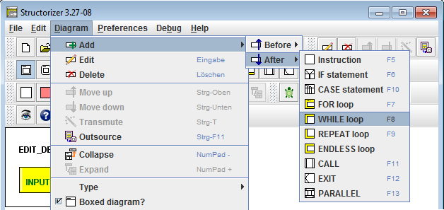
Note: Double-clicking an empty block in the diagram always inserts a new element of the type "Instruction".
Before the element gets actually inserted, the element editor will pop up and expects you to type in the desired content (see sections Elements and Edit Element for details). For certain kinds of elements (loops, alternatives) the text field will be prefilled with the respective default text configured in the Structure Preferences, the caret (or cursor position) will already by placed at the first question mark in the default text (from version 3.32-15 on).
Since version 3.32-11, a little Content Assist may help you with context-related word suggestions.
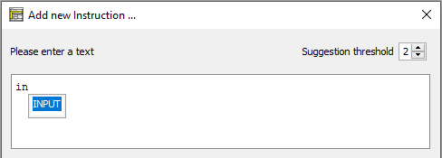
5.3. Edit element
In order to edit the content of an element, you can either double-click on it or simply select the element you want to edit and perform one of the following actions:
- Use the main menu: "Diagram › Edit";
- Right click the element and select "Edit" in the popup menu;
- Just click the <ENTER> key;
- Use the following speed button in the toolbar:
 .
.
Next, the editor window will pop up where you can change the text content of the element or its comment. Hit the "Cancel" button to cancel the action or the "OK" button to commit your changes.
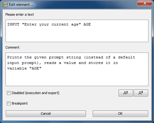
In general, the editor provides two editable parts (with the exception of some types of elements, e.g. FOR loops, see the respective Element description)):
This is the actual content of the element. It is (normally) being displayed in the diagram. There may be syntactical restrictions for what the text part should contain, depending on the kind of the element. Since version 3.32-11 there is an autocompletion function for the text area as described on page Content Assist.
This can be arbitrary text commenting the element's purpose or contents. Comments may be displayed in different ways, though, (see below). They are saved, exported to source etc. And they may even be the starting point for your algorithm design (see Switch text/comments).
The initial focus (input cursor) on opening the editor usually lies on the text input field (if available and editable), but when mode Switch text/comments is active then the focus will initially be located in the comment input field. Hence, the focus will always be in that area the contents of which are currently shown in the diagram.
The font size of the editable text fields can be scaled up or down by the resizing buttons  beneath the comment text field or by entering the respective key combination <Ctrl><Numpad+> or <Ctrl><Numpad-> (requiring the focus being within one of the enabled text input fields).
Since version 3.30-15, text changes in the text and the comment fields are undoable (<Ctrl><Z>) and redoable (<Ctrl><Y>, <Ctrl><Shift><Z>).
On the editor window there are also two checkboxes where you may
- disable / re-enable the element (with respect to execution and export);
- set / unset a breakpoint on this element. If there is a non-zero breakpoint trigger value, the editor will only display it, it cannot be modified here — use the respective menu items or key binding in the diagram as described on the Executor page.
Comment display in the work area
Usually the diagram won't show directly the element comments (unless you activate either "Switch text/comment" or "Comments plus texts" mode).
If an element is equipped with a comment and the "Show comments" mode is active, however, then a vertical gray line is displayed near the left element edge, indicating that there is an inspectable comment. To take a look at the comment just let the mouse hover over the given element, this will pop up a tooltip showing the comment (see illustration below).
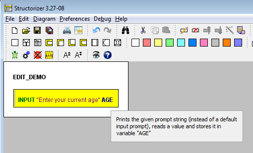
Edit a referenced diagram
For CALL elements and the diagram frame there is a specific service: Both in the context menu and the edit menu there is a menu item "Edit Sub-routine ..." or "Edit included diagram ...", which opens an additional Structorizer window for the referenced diagram (if it is available), such that you may inspect or edit that diagram (either a subroutine or Includable diagram) and its elements "concurrently". You might use key binding <Ctrl><Enter> alternatively.
See CALL or Program/Sub for details.
5.4. Remove element
In order to remove an element, you must first select the element (or the element subsequence) you want to remove. Then you have several options:
- Use the main menu: "Diagram › Delete";
- Right click the element and use "Delete" in the popup menu;
- Hit the key <Del> on your keyboard;
- Use the following speedbutton:
 (in versions before 3.27-08 it used to look like
  ).
).
If you want to reuse the element at a different place or in another diagram then you should cut the element instead, this leaves a copy in the local clipboard:
- Use the main menu: "Edit › Cut";
- Right click the element and use "Cut" in the popup menu;
- Hit the key combination <Ctrl><X> or <Shift><Del> on your keyboard;
- Use the "scissors" speed button in the toolbar:
 .
.
Note: Instead of the <
Ctrl> key you may have to use an OS-specific default command key. Mac users, for example, may have to press the "Apple key" (

) instead of the
<Ctrl> key in the respective
key bindings ...
5.5. Move element
In order to move an element or an element sequence up or down, you must first select the element (or the element subsequence, respectively, see section Diagram) you want to move. Then you have several options:
- Use the main menu: "Diagram › Move up" or "Diagram › Move down";
- Right click the element and use "Move up" or "Move down" in the popup menu;
- Press key combination <Ctrl><Up> or <Ctrl><Down>, respectively;
- Cut an element and paste it into a new location (refer to copy & paste instructions);
- Use the following speedbuttons:
 .
.
You can also simply drag & drop an element onto a new position, even across branches etc. The cursor will change its shape to  on pressing the mouse button if the element at mouse position is ready for dragging. The dragged element will be positioned after the element at drag position when you drop it, unless you held the <Shift> button pressed. In order to insert the moved element before the drag position you simply hold the <Shift> key down on dropping (since version 3.30-13).
When the elements implicated in the drag & drop are marked green, then the drag is permissible:
While they are displayed in red, the drag is invalid:
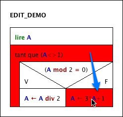
Dragging works only for single elements, not for selected element sequences.
Note: Instead of the <Ctrl> key you may have to use an OS-specific default command key. Mac users, for example, may have to press the "Apple key" ( ) instead of the <Ctrl> key in the respective key bindings ...
5.6. Copy element
You can copy & paste (or cut & paste, see below) single elements or blocks of consecutive elements inside a diagram in the usual ways:
- Select an item (or an element subsequence), go to the menu "Edit › Copy" or press <Ctrl><C> (or, equivalently, <Ctrl><Ins>) on the keyboard or the
 speedbutton in the toolbar. The selected element(s) will now have been copied.
- Next, click on the destination element, then choose the menu item "Edit › Paste" or press <Ctrl><V> (or, equivalently, <Shift><Ins>) on the keyboard or the
 speedbutton in the toolbar. The copied element (sequence) will be inserted after the chosen destination element.
- If several diagrams are parked in Arranger then you may even switch the edited diagram between the copy/cut action and the paste action such that the elements (or sequences) can easily be transferred between several simultaneously open diagrams.
The transfer of elements between several diagrams can be facilitated by opening more than one editor within the same application process. See the Arranger page, the description of the Outsourcing features and the explanation of how to edit a referenced diagram to get an idea of the ways to open additional dependent editor windows within the same application process. (If you have started several independent Structorizer processes, however, then you will find it impossible to transfer an element or subsequence from one of them to another this way, because a process-internal clipboard is used instead of the system clipboard.)
In addition, you may copy an entire diagram (if the Program/Subroutine frame is selected) to the system clipboard from where it may be pasted into an open Arranger or any other Structorizer editor — even if that represents a different process.
In order to cut an element (or subsequence) you want to paste elsewhere use menu item "Edit › Cut", press <Ctrl><X> (or, equivalently, <Shift><Del>) on the keyboard, or the  speedbutton in the toolbar; also see Move element.
Note: Instead of the <Ctrl> key you may have to use an OS-specific default command key. Mac users, for example, may have to press the "Apple key" ( ) instead of the <Ctrl> key in the respective key bindings ...
5.7. Colorize element
Tinting elements
You may freely dye elements in Structorizer, e.g. for better distinction of semantic portions of your algorithm. To do so you must first select the element(s) and then click on one of the "paint box" speedbuttons:

This way you may highlight, emphasize, or visually distinguish parts of a diagram.
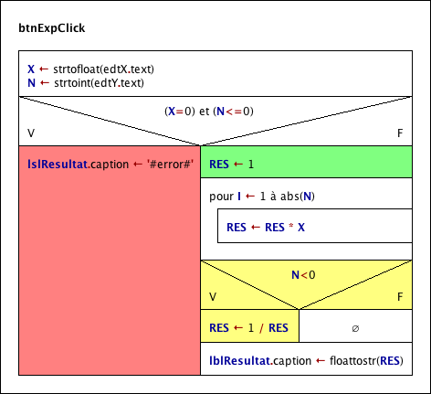
For the above example:
- The red colour is used to mark an instruction that produces an error message.
- The green instruction symbolises a variable initialisation.
- The yellow block inverts the value of "RES" if "N" is less than zero.
There is a specific effect if the coloured element contains a Turtleizer move statement (one of forward, fd, backward, or bk): In this case the element colour will determine the colour of the line drawn by the turtle (where a white element background means a black line, however).
You are by no means limited to the ten default colours in the paintbox toolbar — like an artist you may "mix" your own set of colours for the palette whenever you want via the "colors" preferences. To modify the palette does not change the colour of elements that have previously been dyed with the respective paint box buttons. You can save and reload your favourite sets of ten colours per palette as explained in section Preferences, and reset the original colour set.
Tinting branches
From version 3.32-28 on, you have even the opportunity to apply individual colours to each of the branch selector areas in forking elements (i.e., Alternatives and CASE elements):
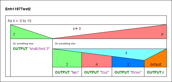
In order to achieve this, first select the branching element:
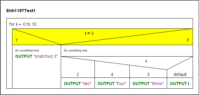
When it has been selected, just click again on the respective selector area. Then this area will be highlighted allone:
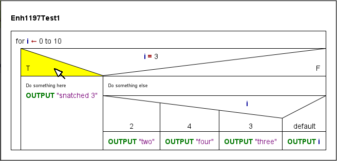
If you now choose a paintbox button then the elected colour will be attached to the selector area (independently of the element colour and possible colours of other selector areas of the same element).
This functionality may be used e.g. to emphasize certain execution path in an appealing way (in the example first the entire Alternative header was made green, the the "F" label area was turned white again, which locally overrides the element colour):
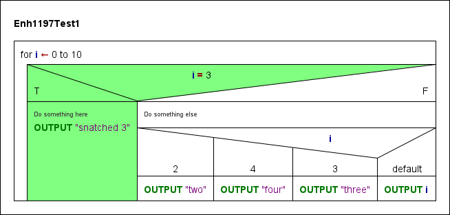
While a forking element or one of its individually dyed selector regions is selected, a specific additional speedbutton in the paintbox toolbar will get enabled (the rightmost and transparent one with a red Andrew's cross in it):

By pressing it you will clear the colour from either all branch selectors of the element (if no specific selector area had been selected) or just the currently selected one, such that the affected selector areas will return to show the common element colour from now on.
Note that an active subselection does not in any way compromise other possible actions the entire element might be subject to (e.g. dragging, removal etc.).
5.8. Collapse element
Motivation and usage
In order to regain overview in large diagrams you may collapse some elements, i.e. minimize their size to a small instruction-like rectangle. This is not a modification of the diagram (and won't be saved) but only a display modification. Hence, collapsing won't be registered in the undo list, either.
To collapse an element (it makes only sense for area-consuming structured elements, actually) you first select it and then choose among the following possibilities:
- Select the menu item "Collapse" in the "Diagram" menu;
- Press the speed button
 in the toolbar (see image below);
- Press the '-' button on the number pad;
- Right-click the element and select the "Collapse" item of the contextual menu;
- Roll the mouse wheel upwards (if the respective mouse wheel mode is enabled).

To expand a collapsed element (i.e. to show it in its original size, shape, and design again), select it and do one of the following equivalent actions:
- Select the menu item "Expand" in the "Diagram" menu;
- Press the speed button
 in the toolbar (see image above);
- Press the '+' button on the number pad;
- Right-click the element and select the "Expand" item of the contextual menu;
- Roll the mouse wheel downwards (if the respective mouse wheel mode is enabled).
In collapsed state, an element won't show any substructure, its colour will turn gray, and just the first line of its very own text will show, followed (or preceded in case of a REPAT loop) by an ellipse ("..."). Lest you should have to guess what element type it may be, all structured collapsed elements will present a little icon in their upper left corner:
A WHILE loop expanded and collapsed
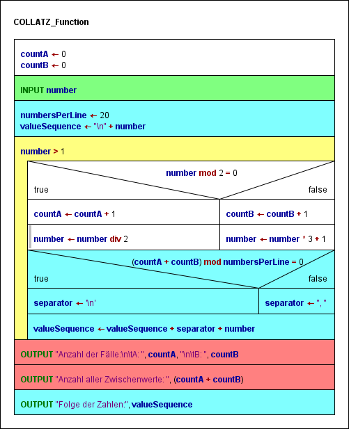 |
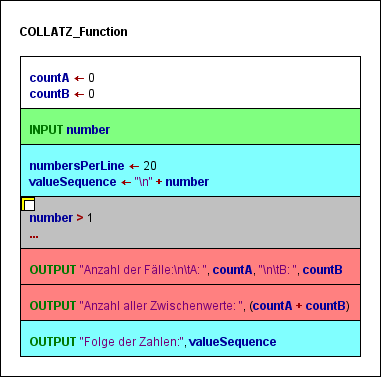 |
| The selected WHILE loop (yellow) is expanded |
The same WHILE loop is collapsed now (gray) |
Note: Collapsing a structured element may change the displayed value of tracked run data or its representation but won't discard or modify the tracked data themselves.
Mouse Wheel Mode
In the "Preferences ›  Mouse Wheel" submenu you can specify what effect the mouse wheel is to have within the Structorizer work area: If the toggle item
  is selected then rolling the wheel up or down will collapse or expand the currently selected element, respectively. Otherwise, moving the mouse wheel will scroll the Structorizer editor canvas vertically or (on most platforms), with the <Shift> key pressed, horizontally. A touchpad will work in the analogous way.
5.9. Transmute element
Overview
The function to transmute (convert) elements or sequences of elements into elements of a different type may facilitate the editing of Nassi-Shneiderman diagrams significantly. This is particularly helpful to make e.g. a subroutine call or an exit operational for the Executor or to merge or split several instructions in order to improve the diagram layout or to allow the setting of breakpoints between instructions that had formed a common Instruction element.
Unstructured (simple) elements (Instructions, CALLs, or EXITs), sequences of simple elements, counting FOR loops, CASE, and IF elements may be transmuted. Simple elements with a single line may change their type. Simple elements with several lines will be split, a sequence of simple elements will be merged. On merging simple elements, the type of element will only be preserved if all elements are of the same type, otherwise the result will be "downgraded" to a multi-line Instruction. A FOR loop or a CASE element will be decomposed (see below).
To initiate a transmutation of the selected element or subsequence you may:
- press the
 button;
- activate the respective menu item "Transmute" in either the "Diagram" or the context menu;
- press the accelerator key combination <Ctrl><T>.
These controls are only enabled if there is a suitable selection (see below).
The following table lists the available conversions depending on the current selection:
Possible transmutations
| Selected |
Lines |
Prerequisites |
Result |
| single Instruction element |
1 |
CALL syntax |
CALL element (same content) |
| single Instruction element |
1 |
Jump (EXIT) syntax |
EXIT element (same content) |
| single Instruction element |
≥ 2 |
|
Sequence of single-line Instruction elements (split)
|
| single CALL element |
1 |
|
Instruction element (same content)
|
| single CALL element |
≥ 2 |
|
Sequence of single-line CALL elements (split)
|
| single EXIT element |
1 |
|
Instruction element (same content)
|
| single EXIT element |
≥ 2 |
|
Sequence of single-line EXIT elements (split)
|
| Sequence of Instruction elements |
|
|
Multi-line Instruction element (merged)
|
| Sequence of CALL elements |
|
|
Multi-line CALL element (not excutable!) |
| Sequence of EXIT elements |
|
|
Multi-line EXIT element (not executable!) |
|
Mixed sequence of Instruction,
CALL, or EXIT elements
|
|
|
Multi-line Instruction element |
| FOR loop |
|
counting style |
WHILE loop with auxiliary instructions |
| CASE element |
|
|
Nested IF elements (possibly with auxiliary assignment) |
| IF element |
|
non-empty FALSE branch |
IF element with flipped branches and negated condition |
All transmutations are undoable and redoable. For some of the transmutations there is even a reverse transmutation, but not for all.
Examples
As shown by the following figures, a single wand button click is sufficient to convert a multi-line instruction element into a sequence of instructions (and vice versa):
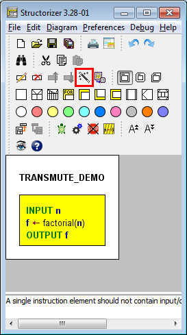

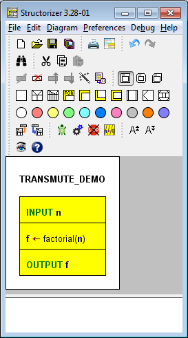
Having selected the second element of the splitting result, a subsequent transmutation would convert the instruction into a CALL element because it matches the syntactic requirements of an executable subroutine Call (see also Executor):
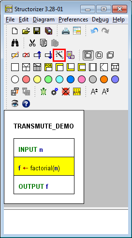

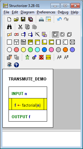
The transmutation of a FOR loop (of "counting" flavour) decomposes it into a WHILE loop with separate initialisation instruction and embedded incrementing/decrementing instruction. This operation is particularly sensible if an additional condition is needed to control the loop. And, of course, in order to demonstrate the equivalence of both constructs.
If the decomposed FOR loop was coloured then all substituting elements will inherit the same colour (see images below after separate transmutation of both inner FOR loops).
Note: There is no reverse transmutation for a FOR loop decomposition (it is only undoable during the current session)! And there is no transmutation for traversing FOR loops (aka FOR-IN loops) by now.
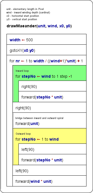

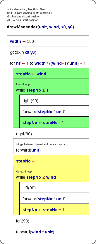
The transmutation of a CASE structure decomposes it into an equivalent set of nested IF statements. If the discriminator is not a variable but some kind of expression to be computed then an instruction element assigning its value to a generically named variable is inserted before the outer replacing IF statement. This way, repeated computation of the discriminating value is avoided, which does not only preserve performance but also consistence. Such a decomposition may be sensible if you have to compare with non-constant values (as are required by a CASE structure) or against intervals. (Besides, the transmutation demonstrates the equivalence of the constructs and the elegance of a CASE structure in comparison.)
If the decomposed CASE element was coloured then all substituting elements will inherit the same colour (see images below — before and after transmutation of a CASE element):
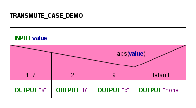

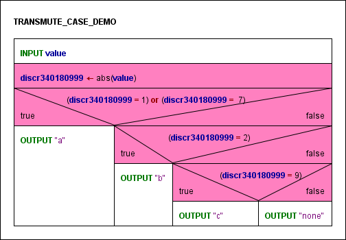
Again, there is no reverse transmutation, i.e. you may not compose nested or chained IF elements to a CASE element automatically.
An IF statement (alternative) with awkwardly formulated condition (e.g. such that you would have to leave the TRUE branch empty — which isn't allowed) may easily be flipped, provided that the ELSE branch hadn't been empty (which would result in an illegal IF element with empty TRUE branch):
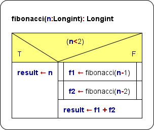

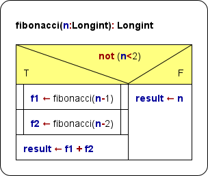
With the current version of Structorizer, the negation of the condition is not very intelligent (as to be seen in the example above, where n≥2 would have been a more sophisticated result), but at least a repeated flip won't inflate the expression with more and more encapsulating not operators. (A later version may perhaps improve the logical inversion.)
Handling of comments on merging, splitting, and decomposing
On merging instructions the transmutation mechanism tries to concatenate the comments of the combined elements in such a way that the resulting multi-line comment can be split and correctly re-assigned to the original instruction elements again. But note that this effort may be spoiled in the following cases:
- The resulting multi-line element is manually edited;
- The resulting multi-line element is merged with further instructions.
If an unambiguous re-distribution of the comment lines is impossible on splitting then the first of the separated instructions will obtain the entire comment while the following elements will end up with an emptied comment.
The comment of a decomposed FOR loop is transferred to the replacing WHILE loop. The two created auxiliary Instruction elements will not inherit comments.
The comment of a decomposed CASE element will be inherited by the first of the replacing elements, i.e. either by the discriminator assignment (if inserted) or by the outermost IF statement.
5.10. Outsourcing
Outsourcing of elements to a subroutine
Since release 3.27 you may select a contiguous subsequence of elements of your diagram and automatically outsource it to a new subroutine just in a flash!
Imagine the following example of a statistical calculation. It starts with the manual input of some numerical values, then computes their average and finally derives the standard deviation.
You may want to decompose this algorithm. Let's start with the standard deviation. Select all elements involved in this part of the computation:
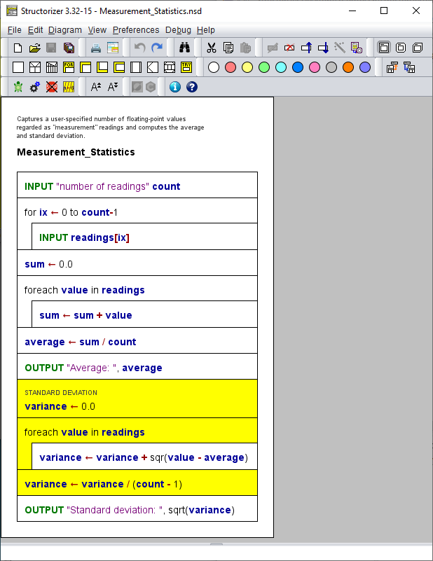
To convert the selected part into a subroutine you may:
- select menu item "Diagram ›
 Outsource",
- select context menu item "
 Outsource", or
- enter <Ctrl><F11>.
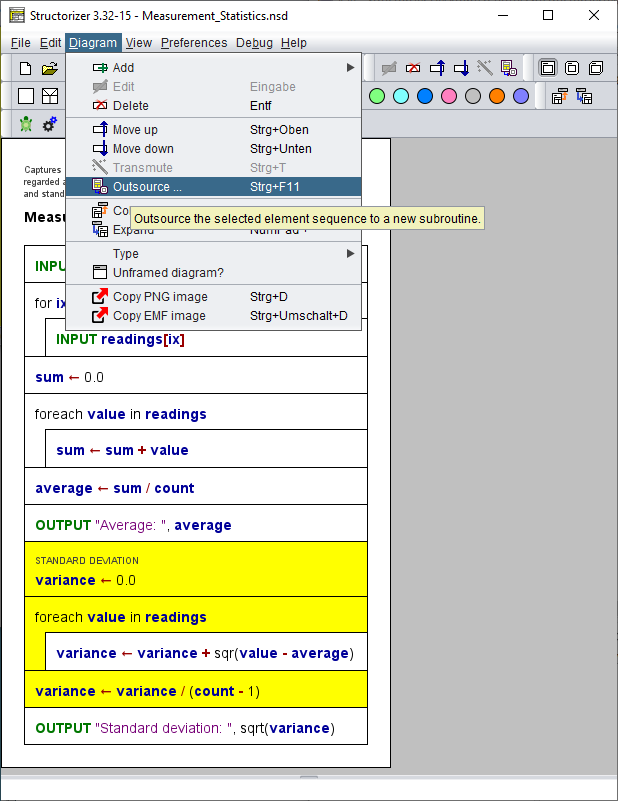
You will simply be prompted for a routine name:
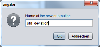
That's all what you have to do (most times, at least)! Structorizer will automatically analyze what arguments the routine needs and whether it is to return a value, then it will move the elements to the new routine created with this signature and also push the routine diagram to the Arranger. If the main diagram had not been in the Arranger before then it will be pushed there, too:
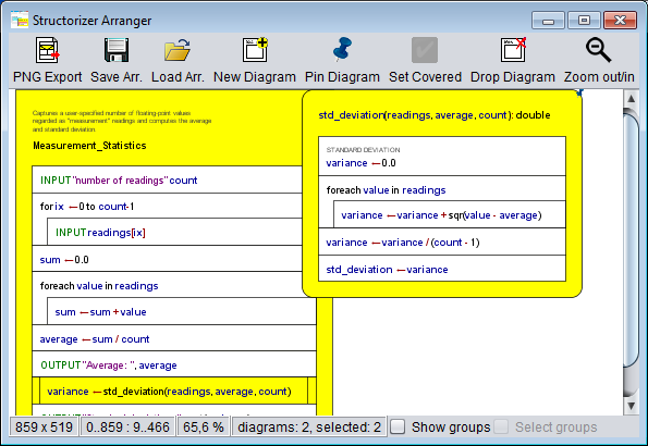
In the original diagram, the extracted elements will have been substituted with the respective routine call. The replacing CALL element is automatically selected (and hence highlighted). Note that the result is immediately ready for execution!
If the parent diagram hadn't resided in the Arranger then a new group will be created named after it (see the red box in the screenshot below). The new subroutine diagram will automatically join all arrangement groups its parent diagram has been member of.
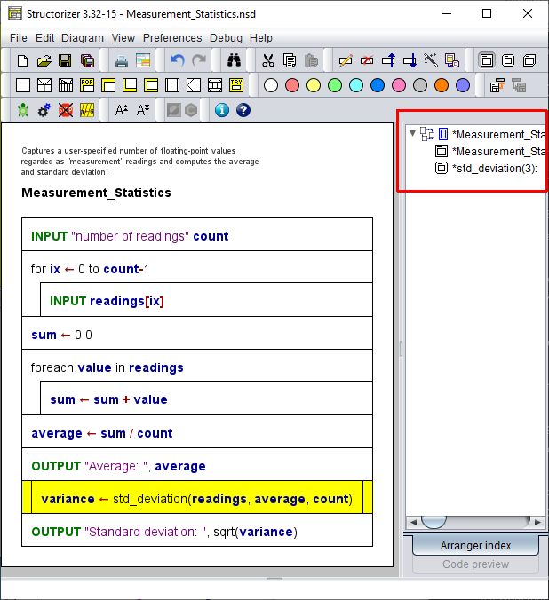
Looks nice? Well, but what about diagram regions that produce more than a single value, on which other parts of the algorithm rely? Let's try with the input part next — it introduces both the count variable and the readings array, which are both used by subsequent code:
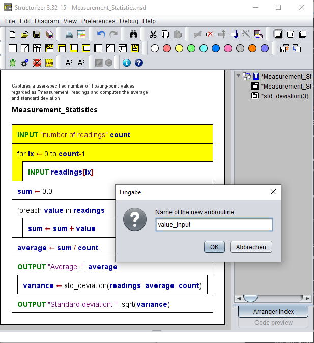
Since the values to be returned might be of different types it would certainly be cleaner to create and share a dedicated record (struct) type for exactly this routine return value, but instead the converter makes use of the ability to fill arrays ad-hoc with values of different types (which is still simpler in Structorizer, but also bound to cause trouble on export to several programming languages, on the other hand).
In Arranger, the new subroutine will also be member of the arrangement group (the bounding box of which can be visualised by switching on the "Show groups" checkbox):
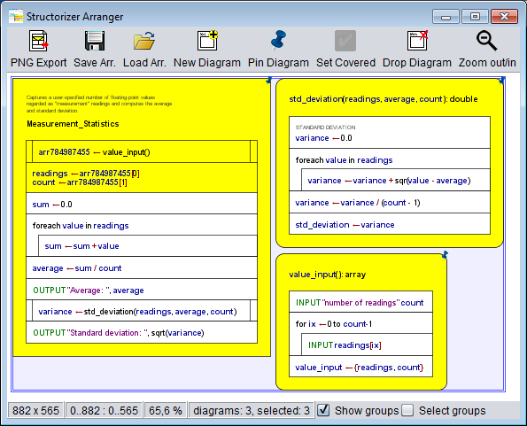
And how is the CALL integrated in the main program? Let's have a look:
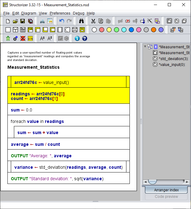
As you can see, an array variable with a generic name is introduced to receive the values from the routine, then the values are extracted one by one and put into the actual target variables. (This method may not look so nice but is very effective in Structorizer. We have to admit, of course, that it may cause trouble on code export to some strictly typed languages, where you would have to make use of record/struct types instead. A future release might make use of the record concept already introduced with release 3.27 here.)
Consequently, outsourcing the average calculation is just as easy as before:
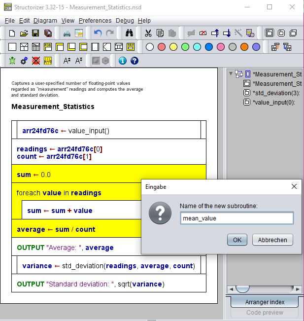
So we get the third subroutine in a blink, too.
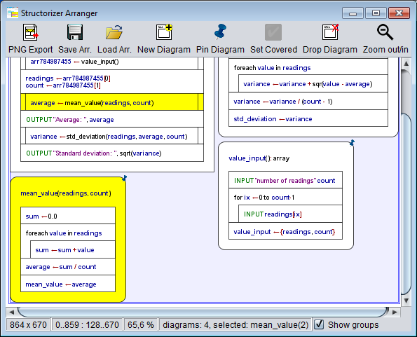
The main program has shrunk a lot, this way:
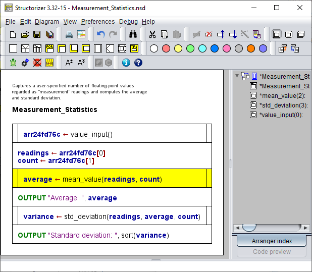
It should not be necessary to mention that the outsourcing can of course be undone in the main routine (and redone etc.). The undoing in the parent diagram will not delete the created subroutines, however. You may simply remove ("drop") them if you want to get rid of them.
Note, on the other hand, that the emerged group of diagrams is consistent now. It is ready to be saved as arrangement, simply by selecting the group entry in the Arranger Index (right panel) and clicking the "Save changes" item in the context menu. You will be offered to store the group either as compressed archive or as a set of nsd files with a referencing arrangement list file:
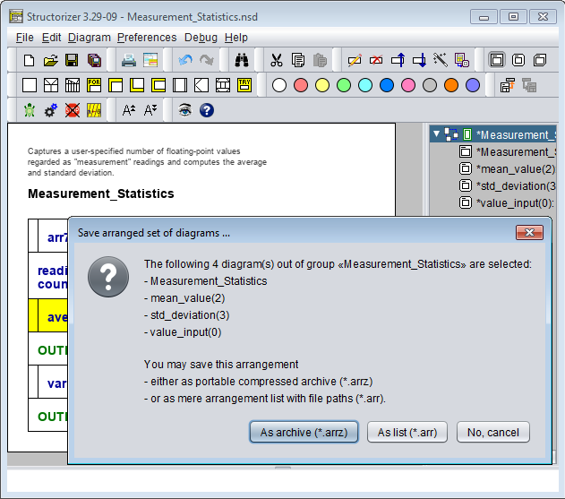
Admittedly, this was only half the truth - there are cases where Structorizer may not cope with correctly identifying the needed parameters and result values. Then you will have to accomplish the result yourself. But we think that even in these cases the "Outsourcing" function will facilitate your job to decompose an algorithm grown too complex. Let's see an example in the following section.
Outsourcing with record types or includables involved
Consider the following algorithm, which simply derives a slightly modified date from a given date (without calendar corrections). Here a record type is involved, which the main program and the outsourced subroutine (from the selected elements) will have to share. You start the outsourcing as described above:
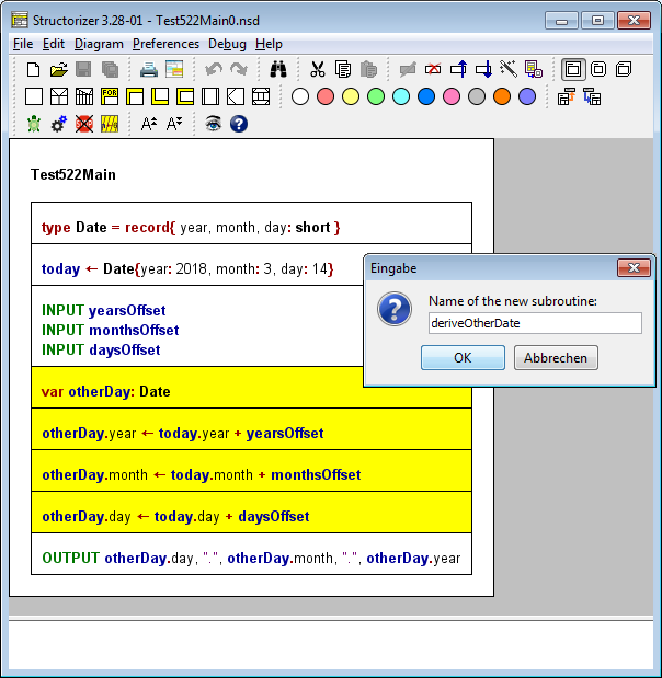
But Structorizer detects that the type Date defined in the main program must also be known to the subroutine diagram and thus decides that it has to be tranferred to an Includable diagram that both main and subroutine need to include. Therefore you will be asked for a name for that additional diagram:
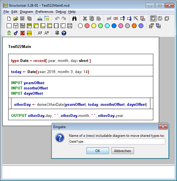
After having commited the question, you will obtain two new diagrams, the includable and the subroutine:
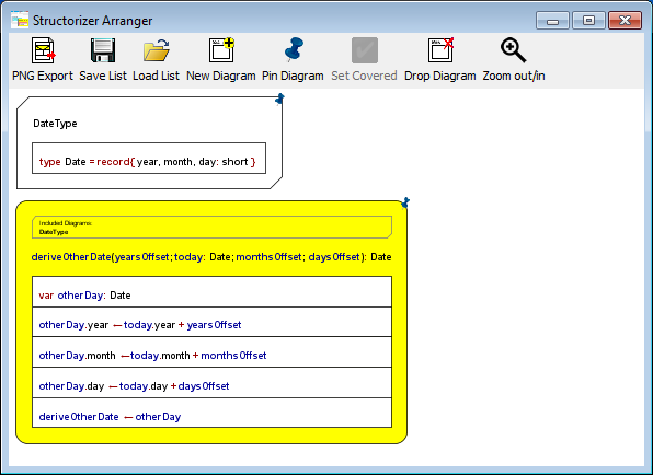
The main program will have changed as follows:
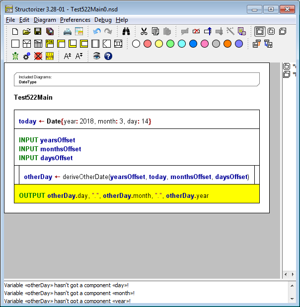
As you can see in the Analyser report list, the result is not quite correct. A record variable cannot simply be introduced by assignment (unless the assigned value is a record initializer). So we must re-introduce a declaration like the one moved to the subroutine (where it is also necessary, so it wouldn't have helped just not to select the declaration before outsourcing — in that case the subroutine would have been defective instead). For the current version of Structorizer an automatic solution of this situation is still slightly too complex.
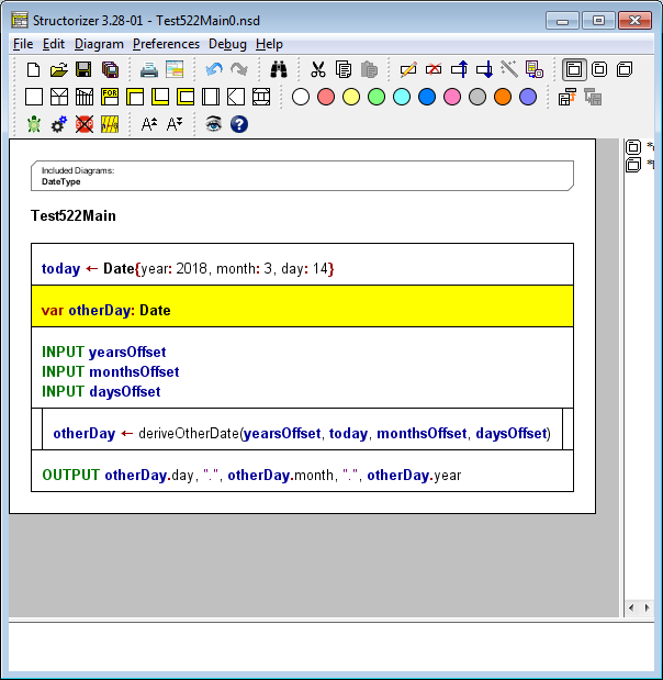
By the way: If the record type had already been included by the main routine (instead of having been defined locally) before outsourcing, however, then the subroutine would have inherited that include item automatically without asking.
Remark with respect to the arrangement groups introduced with release 3.29: On outsourcing, Structorizer ensures that the derived subroutine and a possible includable diagram will automatically be added to all groups the originating diagram is member of, such that consistency is preserved.
Counter-indications against outsourcing
There are algorithm subsets, however, which cannot easily be outsourced. Not surprisingly, they are usually provoked by unstructured diagram elements like Jumps (EXITs). If the selected region of the diagram contains EXIT elements, which intend to direct the control flow to targets outside the selection then we get in deep trouble. Look at the following nonsense example. It contains a CASE selection with several kinds of outbreaking elements — exiting the inner loop, the outer loop, the entire application, or the current routine or program, respectively:
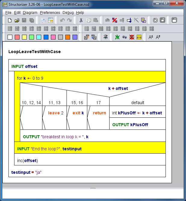
If we liked to outsource the selected elements then three of the Jumps point outwards the subset, only the empty Jump (equivalent to leave) has a target inside the selection: the input instruction beneath the FOR loop. The exit command is not a problem, either — its semantics is independent of its location, it will always abort the entire execution. With the 2-level leave it is different: its target is the REPEAT loop, which will be outside the routine and hence unreachable, the leave 2 instruction is going to be illegal therefore. The return instruction, on the other hand, will change its semantics drastically: Instead of ending the outer program it would now just leave the subroutine, this way compromising the program logic. (And there is no easy way to maintain or restore the original logic.)
Structorizer tries to detect such cases and vividly warn off outsourcing element sets of that kind:
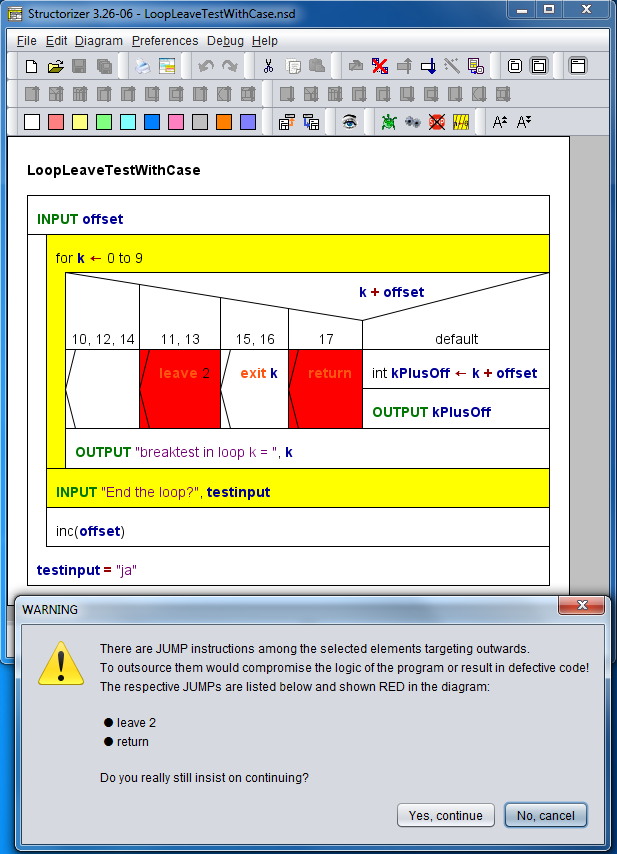
If you really know what you do and you have an idea how to mend the defects provoked by the outsourcing then you may go on, otherwise you better back off.
Note that Jump elements of type throw (exit on error) don't usually cause trouble because the TRY context of the replacing CALL element remains the same.
5.11. Disable element
Since version 3.25-03 you have the opportunity to disable elements in the diagram without having to delete them. Disabled elements will simply be skipped on execution, ignored by the Analyser, and will appear as outcommented sections in exported source files.
In the diagram they are shown with a hatched texture:
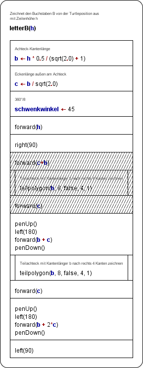
To disable an element or an element sequence, select the elements and then you have these opportunities:
- Activate menu item "Debug › Disable";
- Right-click an element and activate the Disable item in the popup menu;
- Press the toolbar button
 ;
;
- Press the accelerator key <Ctrl><7>.
For a single element, you may also open the Element editor (e.g. by double-clicking the element) and tick the checkbox "Disabled (execution and export)", see screenshot further below.
The same actions are used to re-enable selected disabled elements. If you select a subsequence of elements, which are partially disabled, then the above actions will turn all of the elements disabled first. The next action would enable all of them and so forth.
If you disable a structured element (e.g. a loop or alternative) then of course all contained substructure is indirectly disabled as well and will also be shown in hatched style (except empty element sequences):

Nevertheless, elements of a disabled substructure can still be disabled individually (their disabled state would then remain when that of the containing structure is lifted). The checkbox "Disabled (execution and export)" in the element editor will always show the individual state rather than the inherited one (see screenshot below). Of course it doesn't play a role whether an element inheriting disabled state is disabled individually as long as the superstructure stays disabled. (You cannot effectively enable an element, the superstructure of which is disabled.)

Note that you cannot disable the Root element of a diagram (and thus the entire algorithm). Call elements representing a method declaration after some code file import from an object-oriented language (e.g., Java or Processing, with import option "Import variable (and method) declarations" activated) will permanently be disabled and cannot - by any means - be re-enabled (also see Java Code Import).
5.12. Word-wrap lines
Instruction lines or e.g. conditions of loops or alternatives may get pretty long if the involved expressions are complex. This extends the elements and may lead to a very wide diagram, which compromises overview and manageability.
Since version 3.27, you may effectuate a "soft" line break. To split a long line into several lines (line parts) without losing logical contiguousness you simply place a backslash at the end of each (but the last) part of the line. After code import, however, it can easily become a horrible task if there are lots of overlong lines.
Hence, version 3.28-11 introduced two mechanisms to help coping with it:
- There is a new import option that allows to force the automatic insertion of such "soft line breaks" as soon as a configurable maximum line length is going to be exceeded (see Import options).
- A new menu item in the "Edit" menu provides the means to re-adjust the text lines of just a selected span of elements of a diagram (and possibly their substructure elements) with a new length limit.
This approach (the second opportunity in particular) allows not only to mend the result of a forgotten length limit on code import but also to apply different length limits to different parts of the diagram. Elements neither selected nor being part of the subtree of a selected element are not affected, nor has a readjustment of the lines any impact on other diagrams or elements added later to the diagram.
With the menu-related re-breaking tool too rigidly broken lines may also be re-joined to fit into a larger line limit:
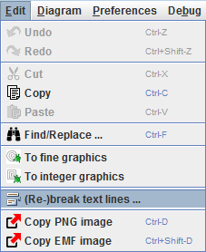
After having chosen the menu item, a little dialog will pop up:
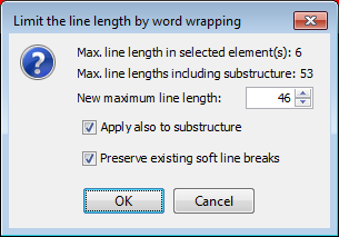
At top it shows the detected maximum line lengths in the selected range of elements, both for the directly selected elements (flat retrieval) and with all substructure of the selected elements included ("deep" retrieval).
Now you are to specify the new line length limit via the spinner control, to decide whether only the selected elements themselves are to be affected (flat mode) or their embedded sub-elements as well (recursive or deep mode). Last but not least you may specify to respect the currently placed soft line breaks (backslashes at the line end); this makes only sense if the new length is less than the current maximum length, otherwise there wouldn't be any change.
Below you see an example of an element with very complex string concatenation expression, first spilt with a line length 255, then with length 80:

You see that the line breaking is actually a word wrapping taking into account the syntactic structure of the line. Literals or names will never be split.
It should be mentioned, however, that very long element comments are not addressed by this assistence, i.e., diagrams may still be stretched by comment lines. Unfortunately a similar word wrapping mechanism for comments isn't available by now. But comments can only stress the element width while the chosen display mode shows them within the elements.
5.13. Print
Toolbar button  or menu item "File › Print" may be used to print the diagram to some installed printer. Key binding <Ctrl><P> has the same effect. First a very simple "Print Preview" will open, showing the diagram embedded in a page of the standard printer format (usually DIN A 4 portrait by default):
Note that e.g. element selection highlighting is reflected in the print preview and the resulting print.
Gray lines symbolize the page margins in the preview (they will not of course occur in the print result). The widths of the horizontal (left / right) and vertical (top / bottom) margins in pixel units are displayed at the bottom bar and may be adjusted via the respective spinner fields. The effect will immediately be shown in the preview. The margin width is limited to 72 pixels at maximum.
You may modify the zoom of the preview via the leftmost control in the bottom bar but this does not modify the size of the diagram with respect to the page size. If you want to enlarge the diagram for printing, you can achieve this by modifying the font size in the work area before.
Via the "Toggle Orientation" button you may alter the page orientation from portrait to landscape or vice versa:
The diagram will automatically be downscaled to fit between the page margins if necessary.
The preview does not take into consideration a specific printer configuration as the choice of the actual printer is only offered after having pressed the "Print" button in the preview dialog. Depending on the capabilities of the printer driver, you may possibly have an opportunity to scale the print to the actually chosen paper format then.
It may make more sense to export the diagram as picture of a suited file format and print the resulting graphics file via some standard image viewer, though. This will give you more flexibility.
6. Syntax
Structograms are intended to be syntax-free, i.e., the contents of the standardized algorithmic elements may be any text, pseudo-code, or whatever seems to make sense to describe the meaning of an algorithmic step. Whereas purists (see Use Cases) may even regard the placement of any kind of code instead of verbal descriptions in a diagram as sinful, you will certainly agree that e.g. "S ← A + B" is more readable than "Let S be the sum of A and B" for such a simple algorithmic step after all. And less ambiguous, too.
So if you prefer a more symbolic element content and then bother to adhere to certain syntactical conventions imposed by Structorizer for the instruction texts, then you can benefit a lot from the many Structorizer features (like Executor, Analyser, Code Export etc.), which help to verify an algorithm or to derive actual code. These syntactical conventions are a simplified mixture of usual programming languages, with some specific additions (and limitations). Programmers will therefore be quite familiar with most of them, though they will differ slightly from their respective favourite programming language. This suggested syntax will be exemplified in this chapter.
Overview of the remaining subsections of this manual page:
An additional section explains the differing and constrained syntax specifically supported for the provisional ARM generator (introduced as an experimental feature with version 3.32-02):
6.1. Basic Concepts
Recursive "Definition"
An essential concept is that of an expression. An expression describes a (not necessarily numeric) value or the operations to compute a value from other values by means of functions and operators in a more or less natural way. Obvious examples of expressions are:
4 + 7
r * sin(x)
sqr(a + b)
Below there is a semi-formal recursive syntax introduction, where in some cases sort of extended Backus-Naur form is used as a well-known description format (though not quite exact here). Metasymbols are:
- angular brackets <, > enclose a non-terminal concept defined by grammar rules,
- definition symbol ::= separates the concept to be defined from the replacing symbols,
- vertical bars | separate alternative rules within a combined rule,
- parentheses (, ) group e.g. alternative syntactic parts within a rule,
- brackets [, ] enclose optional parts,
- {, } enclose iterated parts within a rule.
Where the above characters are not meant to be meta-symbols but terminal symbols (actual characters in the defined language) they will be underlined to mark the difference.
Atomic expressions are literals and identifiers.
Literals
- The keywords
true and false are Boolean literals.
<literal_bool> ::= true | false
- A sequence of digits possibly preceded by a sign is an integer literal:
<digit> ::= 0|1|2|3|4|5|6|7|8|9
<literal_int> ::= [+|-] <digit> {<digit>}
- A sequence of digits and letters A...F or a...f after a 0x prefix is a hexadecimal integer literal:
<hex_digit> := <digit>|A|B|C|D|E|F|a|b|c|d|e|f
<literal_hex> ::= 0x<hex_digit> {<hex_digit>}
- An integer literal followed by an 'L' character is a long integer literal.
<literal_long> ::= <literal_int>L
- A sequence of digits with a decimal point or an exponential postfix is a floating-point literal; the keyword
Infinity and the symbol ∞ are also floating-point literals (since version 3.30-15):
<literal_float> ::= <literal_int> . <digit>{<digit>} [ E [+|-] <digit>{<digit>} ]
| [+|-] . <digit> {<digit>}[ E [+|-] <digit>{<digit>} ]
| Infinity | ∞
- A single printable character (except a single quote) enclosed in apostrophes (i.e., single quotes) is regarded as character literal:
<literal_char> ::= '<character>'
But well, certain escape notations as e.g. '\n', '\t', '\0', '\'', and '\u0123' are also valid character literals.
- Other character sequences enclosed in single or double quotes are string literals (if it's not a character literal); a string literal may also contain certain escape sequences (in particular, the enclosing delimiter, i.e. a single or double quote, respectively, must be escaped with preceding backslash if occurring within the string literal content).
<literal_string> ::= " {<character>} " | ' {<character>} '
- Integer, long, and floating-point literals may together be qualified as numerical literals:
<literal_num> ::= <literal_int> | <literal_hex> | <literal_long> | <literal_float>
Examples:
- true is a Boolean literal, meaning the logical value TRUE.
- -12 is an integral meaning the obvious value of minus twelve.
- 12.97 and -6.087e4 are non-integral (floating-point) numeric literals.
- '9' is not a numeric but a character literal.
- "Attention!" and 'more than 1 character' are string literals.
- "He called me \"moron\" when I left." and 'is"ok' are valid string literals, "oh"no" ist not.
- 'a' is a character literal whereas "a" is a string literal.
- ∞ is a floating-point (double) literal, meaning an infinite positive value (same as Infinity).
Identifiers
An identifier is a name for certain concepts. In contrast to literals, identifiers require some user-specific declaration or introduction that associate them with a storage place, a value, or e.g. type.
- A contiguous sequence of ASCII letters, digits and underscores, ideally beginning with a letter, not at least beginning with a digit, is an identifier:
<letter> ::= A|B|C|...|Z|a|b|c|...|z
<identifier> ::= (_|<letter>){_|<letter>|<digit>}
Examples:
- kill_bill is an identifier, off the record is not (there must not be spaces within).
Infinity, true, and false are not regarded as identifiers, because they are reserved as literal keywords.
Expressions
- Literals (see above) are (atomic) expressions.
- Variable Designators are (atomic) expressions specifying a storage location associated to a variable or some structural part of it, such as an element of an array variable or a component of a compound (record/struct) variable. Since data structures may be nested, variable designators may be a long sequence starting with an identifier (the variable name), followed by many accessors (bracket-enclosed index lists or dot-linked component selectors). Semantically, a variable designator is only valid if the sequence of accessors corresponds to the nested structure of the variable, specified e.g. by a variable declaration (usually related to type definitions), initialisation, or assignment.
<var_desig> ::= <identifier> | <var_desig> <accessor>
<accessor> ::= . <identifier> | [ <int_expr_list> ]
<int_expr_list> ::= <int_expr> { , <int_expr> }
An <int_expr> is just an <expression> the value of which has to be an integer.
Examples:
person
today.month
readings[k]
staff[i+5].date_of_birth.year
chess.board[row, column]
matrix[i][j][k]
- A function call is an atomic expression. It is formed by an identifier followed by a pair of parentheses, which enclose a (possibly empty) comma-separated list of expressions, may be a function call. Note: Though procedure calls look quite the same (see below), functions return a value when called, whereas procedures don't. Hence, procedure calls are not expressions but statements (see below).
You find a list of provided built-in functions and procedures in the User Guide.
<func_call> ::= <identifier> ( <expression_list> )
<expression_list> ::= | <expression_list> , <expression>
Examples:
sin(alpha)
copy("comparsery", 5, 4)
- Expressions joined by suited operator symbols are expressions. You find a table of accepted operator symbols in the Structorizer User Guide. The following recursive rules reflect operator precedence.
<factor> ::= [ + | - ] <atomic_expression>
<not_expr> ::= (not | !) <atomic_expression>
<mult_expr> ::= <factor> | <mult_expr> ( * | / | div | mod | % ) <factor>
<add_expr> ::= <mult_expr> | <add_expr> ( + | - ) <mult_expr>
<log_expr> ::= <add_expr> ( = | == | <> | < | > | <= | >= ) <add_expr> | <not_expr>
<log_and_expr> ::= <not_expr> | <log_and_expr> ( and | && ) <log_expr>
<log_expression> ::= <log_and_expr> | <log_expression> ( or | || | xor ) <log_expression>
<cond_expr> ::= <log_expression> ? <expression> : <cond_expr>
- An expression enclosed in parentheses is an atomic expression.
Examples:
(23.5)
(a[i])
(23 * (17 + length("some text")))
- A comma-separated list of expressions as described above, enclosed in braces, is an array-initializing expression (only usable in assignments, as routine arguments, as input, and in FOR-IN loops). The list may be empty.
<init_expr_a> ::= { <expression_list> }
Examples:
{2, 3, 5, 7, 11, 13, 17}
{}
{"Fruit", "flies", "like", "banana"}
{17.3*4, sqrt(2.9), pow(1.2, k), log(val)}
- A defined record type identifier, followed by a pair of braces that include comma-separated triples of a declared component identifier, a colon, and an expression is a record-initializing expression.
<init_expr_r> ::= <identifier> { <comp_init_list> }
<comp_init_list> ::= | <comp_init_list> , <comp_init>
<comp_init> ::= <identifier> : <expression>
Examples:
Date{2023, 10, 14}
Employee{"Dough", "John", Date{1995, 12, 24}, HEAD_OF_DPT}
UnitValue{130, KMPH}
- Since version 3.28-06, a smart record-initializing expression is supported. It still starts with a defined record type identifier, but the following pair of braces may contain a mere list of expressions as in the array-initializing expression. In this case the values will be assigned to the components in order of their declaration in the respective record type definition. There must not be more expressions in the list than components in the type (but there might be less). It is also allowed that an incomplete expression list is followed by a sequence of comma-separated triples of name, colon, and expression as before. Simple expressions following a component initialization triple, however, are ignored (examples see Records).
<comp_init> ::= [ <identifier> : ] <expression>
Summary:
<atomic_expression> ::= <literal> | <var_desig> | <func_call> | ( <expression> )
<expression> ::= <add_expression> | <log_expression> | <init_expr_a> | <init_expr_r> | <cond_expr>
- There are no other expressions.
- The type of an expression is derived from the used operators and operand expressions and functions. (The incorrect BNF snippets above were simply to give a vague idea how type deduction might work in a grammar-defined way. To provide a halfway exact parsable grammar would require much more non-terminal vocabulary and hundreds of BNF rules with the major weak point of undeclared variables.)
- A Boolean expression may be constructed with comparison operators or consist of operands with Boolean value etc.
- On execution, the syntax is context-sensitive, i.e. the actual variable and constant types decide whether the expression is well-formed and can be evaluated. But then its result type is unambiguous.
Consider the following diagram. Looks pretty simple and straightforward, right? Entered 5 and 7, the result will be 12, okay. But wait — what if the user enters an array or record initializer? Then the yellow expression would be completely illegal! If one of the inputs is a string then variable c would be a string, otherwise with one of a or b being false or true illegal again, with two numeric values c would become a floating point number if a or b had been entered with a decimal point, else possibly an integer result. And so on.
Statements
Statements describe some executable action. In many traditional programming languages, statements are no kind of expression, neither they are in Structorizer. They may contain and use expressions. Elements of Nassi-Shneiderman diagrams represent statements, not expressions. They may be
simple (atomic:
Instruction,
Call, or
Jump elements) or
structured (i.e., they contain nested elements, any remaining kind of element).
- An assigment is a statement (see Instruction in the user guide)
<assignment> ::= <var_desig> ( <- | := ) <expression>
In some programming languages (like C), assignments are expressions themselves and may thus be used as terms in more complex expressions, this does not hold in Structorizer, though.
- A procedure call is a statement (instruction). Depending on whether the referenced procedure is a built-in one or refers to a user-defined subroutine diagram, either an Instruction element or a Call element is required to place the procedure call.
<proc_call> ::= <identifier> ( <expression_list> )
- Further statements are:
- input statement
<input_statement> ::= <input> [ <literal_string> [,] ] [ <var_desig> { , <var_desig> } ]
- output statement
<output_statement> ::= <output> <expression_list>
- In a wide interpretation (e.g. C etc.), type definitions, constant definitions, and variable declarations might also be regarded as statements. In a stricter sense (e.g. Pascal), they are not. Structorizer places them in Instruction elements, so they might be subsumed under the concept "statement" here.
- constant definition
<const_definition> ::= const <identifier> ( <- | := ) <const_expression>
<const_expression> is just an expression the value of which only depends on literals and defined constants.
- type definition
<type_definition> ::= type <identifier> = ( <record_spec> | <enum_spec> | <array_spec> | <identifier> )
<record_spec> ::= ( record | struct ) { <comp_decl> { ; <comp_decl } }
<array_spec> ::= array <dim_ranges> of (<array_spec> | <identifier>) | <identifier> <dim_sizes>
<enum_spec> ::= enum { <enum_item> { , <enum_item> } }
<comp_decl> ::= <identifier> { , <identifier> } : ( <array_spec> | <identifier> )
<enum_item> ::= <identifier> [ = <const_expression> ]
<dim_ranges> ::= | [ <dim_range> { , <dim_range> } ]
<dim_range> ::= <literal_int> .. <literal_int> | <const_expression>
<dim_sizes> := [ <const_expression> { , <const_expression> } ]
- variable declaration may be a mere declaration or an initialised declaration. In the latter case (and only in the latter case) either Pascal-/BASIC-like or C-like style is supported. For a mere declaration (i.e. without initial value assignment), only Pascal/BASIC style is available.
<variable_declaration> ::= <var_decl> | <var_init1> | <var_init_c>
<var_decl> ::= ( var | dim ) <identifier> { , <identifier> } ( : | as ) (<array_spec> | <identifier>)
- initialised variable declaration
<var_init1> ::= ( var | dim ) <identifier> ( : | as ) (<array_spec> | <identifier>) ( <- | := ) <expression>
<var_init_c> ::= <identifier> <identifier> [ <dim_sizes> ] ( <- | := ) <expression>
- Return, leave, exit, and throw statements are Jump statements, represented by a specific type of element in structograms.
<return_stmt> ::= return [ <expression> ]
<leave_stmt> ::= leave [ <literal_int> ]
<exit_stmt> ::= exit <add_expr>
<throw_stmt> ::= throw [ <add_expr> ]
<jump_statement> ::= <return_stmt> | <leave_stmt> | <exit_stmt> | <throw_stmt>
<statement> ::= <assignment> | <proc_call> | <input_statement> | <output_statement> | <jump_statement> | <const_definition> | <type_definition> | <var_declaration>
- Any composed statement (i.e., a basic algorithmic structure like an alternative or a loop) is represented by a specific kind of structogram element and doesn't need a syntax explanation therefore, with the exception of FOR loops.
<for_loop_header> ::= <for> <identifier> ( <- | := ) <add_expr> <to> <add_expr> [ <by> <literal_int> ]
<for_loop_header> ::= <foreach> <identifier> <in> <list_expr>
<list_expr> ::= <qual_name> | <init_expr_a> | <expression_list>
6.2. Built-in Assets
As the Executor is a Java-based interpreter, it should understand most Java commands. Besides this, it has been designed to work with basic Pascal syntax.
Reference tables
Here are the (not necessarily complete) lists of usable operators and built-in functions:
Supported Operators
| Symbol |
Alternative symbols |
Description (iff = if and only if) |
| <- |
:= |
Value assignment (including automatic variable declaration; <- displayed as ← in standard highlighting mode, both displayed as = in C operator mode) |
| + |
|
Addition or positive sign (or string concatenation as in Java) |
| - |
|
Subtraction or negative sign |
| * |
|
Multiplication |
| / |
|
Division (effect depends on operand types: with two integer operands, it results in an integer division) |
| div |
|
Integer division (among integer operands, as in Pascal; displayed as / in C operator mode) |
| mod |
% |
Modulo operation among integer operands (i.e. results in the integral division remainder; displayed as % in C operator mode) |
| = |
== |
Comparison operator (true iff both operands are equal; displayed as == in C operator mode) |
| <> |
!=, ≠ |
Comparison operator (true iff both operands differ; displayed as ≠ in standard highlighting mode, as != in C operator mode) |
| < |
|
Comparison operator (less than) |
| > |
|
Comparison operator (greater than) |
| <= |
≤ |
Comparison operator (less than or equal to; displayed as ≤ in standard highlighting mode, as <= in C operator mode) |
| >= |
≥ |
Comparison operator (greater than or equal to; displayed as ≥ in standard highlighting mode, as >= in C operator mode) |
| and |
&& |
Logical AND (true iff both Boolean operands, e.g. comparisons, evaluate to true; displayed as && in C operator mode) |
| or |
|| |
Logical OR (true iff at least one of the two Boolean operands evaluates to true; displayed as || in C operator mode) |
| not |
! |
Logical negation (true iff the Boolean operand evaluates to false; displayed as ! in C operator mode) |
| xor |
^
|
Bitwise exclusive OR between integral numbers (displayed as ^ in C operator mode),
may also be used for logical XOR, but one of <>, !=, ≠ should be preferred in this case
|
| & |
|
Bitwise AND between integral numbers |
| | |
|
Bitwise OR between integral numbers |
| ˜ |
|
Bitwise negation of an integral number |
| << |
shl |
Leftshift operator: m << n results in the integer value where all bits of integer m were shifted left by n |
| >> |
shr |
Rightshift operator: m shr n results in the integer value where all bits of integer m were shifted right by n
|
| ? : |
|
Ternary conditional expression: If the Boolean expression before the question mark is true, then the result will be the value of the expression between ? and :, otherwise the value of the expression after the colon. |
Most operators are binary operators in infix notation, i.e. the operator symbol is placed between its two operands, e.g. a + 3; the operators not and ~ are unary prefix operators, i.e. they are placed before their single operand, e.g. not isDifficult, whereas the operator symbols + and - may either be binary infix (addition, concatenation, or subtraction) or unary prefix operands (sign). The conditional operator pair is ternary as it combines three expressions as operands, e.g.: text ← (b > 17.3) ? "large" : "small".
Operator precedence rules (for the Executor) are similar to those of Java or C:
Operator Precedence (from highest to lowest)
| Category |
Operators |
Associativity |
| Unary |
+, -, !, not, ˜
|
← Right to Left
|
| Multiplicative |
*, /, div, %, mod
|
Left to Right → |
| Additive |
+, -
|
Left to Right → |
| Shift |
<<, shl, >>, shr
|
Left to Right → |
| Relational |
<, <=, ≤, >, >=, ≥ |
— |
| Equality |
=, ==, <>, !=, ≠ |
Left to Right → |
Bitwise AND
|
& |
Left to Right → |
XOR
|
^, xor
|
Left to Right → |
Bitwise OR
|
|
|
Left to Right → |
Logical AND
|
&&, and
|
Left to Right → |
Logical OR
|
||, or
|
Left to Right → |
| Conditional |
? :
|
← Right to Left |
| (Assignment) |
<-, :=
|
— |
This means that e.g. logical operators like and have lower precedence than comparison operators. But be aware that this does not necessarily hold for languages like Pascal, which have much less priority levels, such that e.g. the and operator ranks like multiplication above comparison operators. Hence, an expression like
a = 3 and b < 5
may work perfectly in the Executor but will be illegal in exported Pascal code! So better use parentheses to avoid ambiguity (the code generators can hardly read your intentions):
(a = 3) and (b < 5)
Note: Incomplete and abbreviated comparisons like in
a > 2 and < 17
or
2 < a < 17
(the upper example has an incomplete comparison after the and operator, the lower "expression" would actually try to compare the Boolean result of comparison 2 < a with the numerical value 17) are illegal in Structorizer — as they are in most (but not all) high-level languages.
Like in C or Java, you may directly apply some arithmetic operators to character values, but the result will always be a numeric value: subtracting two characters will compute their code difference, but adding or subtracting an integer offset to or from a character will not result in a character but in its numerical code:
'8' - '0' evaluates to 8 alright,
'A' + 17 will not result in 'R' but in 82
( it requires a built-in function to obtain the character itself: chr('A' + 17) )
Built-in Numerical Functions
| Function |
Description |
| abs(x) |
absolute value of number x; |x| |
| min(x, y) |
minimum of numbers x and y |
| max(x, y) |
maximum of numbers x and y |
| round(x) |
nearest integral number to number x (result is of an integral type)
|
| ceil(x) |
smallest integral number greater than or equal to number x (result is of a floating-point type, though) |
| floor(x) |
greatest integral number less than or equal to number x (result is of a floating-point type, though) |
| sgn(x) |
signum of number x: either -1, 0, or 1 (depending on the sign of x)
|
| signum(x) |
like sgn(x) but returning a floating-point value
|
| sqr(x) |
square of number x; x * x |
| sqrt(x) |
square root of number x (illegal if x is negative) |
| exp(x) |
exponential value with the Euler number e as base and x as exponent: ex |
| log(x) |
natural logarithm (i.e. based on the Euler number e) of number x; ln x; logex
|
| pow(x, y) |
computes x to the power of y (where x, y, and the result are floating-point numbers): xy |
| cos(x) |
cosine of x where x is to be given in radians |
| sin(x) |
sine of x where x is to be given in radians |
| tan(x) |
tangent of x where x is to be given in radians |
| acos(x) |
arcus cosine of x (inverse cos function) where x must be between -1.0 and +1.0, the result will be in radians
|
| asin(x) |
arcus sine of x (inverse sin function) where x must be between -1.0 and 1.0, the result will be in radians
|
| atan(x) |
arcus tangent of x (inverse tan function), result will be in radians (as with asin, acos)
|
| toRadians(x) |
converts angle x from degrees to radians |
| toDegrees(x) |
converts angle x from radians to degrees |
| random(n) |
returns an integral pseudo-random number in the range between 0 and n-1 for positive n, or between n+1 and 0 for negative n
|
Built-in Non-numerical Functions
| length(s: string): int |
returns the number of characters the string s consists of. |
| length(a: array): int |
returns the number of elements the array a consists of. |
lowercase(c: char): char
lowercase(s: string): string |
returns a lower-case representation of character c
returns a string representation of string s where all letters are converted to lowercase |
uppercase(c: char): char
uppercase(s: string): string |
returns an upper-case representation of character c
returns a string representation of string s where all letters are converted to uppercase |
| pos(sub: string; s: string): int |
returns the first starting position of substring sub within string s (position ≥ 1 if any, otherwise 0). |
| copy(s: string; i: int; n: int): string |
returns the substring of string s that starts at character postion i (i ≥ 1) and has at most n characters |
split(s: string; sep: string): array of string
split(s: string; sep: char ): array of string |
breaks the string s around each occurrence of substring or character sep into pieces (some may be empty) and returns them as array |
| trim(s: string): string |
returns the trimmed string s, i.e. without leading and trailing whitespaces
|
| strcmp(s1: string, s2: string): int |
returns -1, 0, or +1 if string s1 is lexicographically less than, equal to, or greater than s2, respectively |
| ord(c: char): int |
returns the ASCII code of the character c (or of the first character of string c) |
| chr(n: int): char |
returns the ASCII character coded by number n |
| isArray(value): bool |
returns true if the argument is an array |
| isString(value): bool |
returns true if the argument is a string |
| isNumber(value): bool |
returns true if the argument is an integral or floating-point number |
| isChar(value): bool |
returns true if the argument is a character |
| isBool(value): bool |
returns true if the argument is a Boolean value |
Built-in Procedures
| Procedure |
Description |
| inc(v) |
increments variable v by one; equivalent to: v ← v + 1 |
| dec(v) |
decrements variable v by one; equivalent to: v ← v - 1 |
| inc(v, i) |
increments variable v by number i; equivalent to: v ← v + i |
| dec(v, d) |
decrements variable v by number d; equivalent to: v ← v - d |
| randomize() |
is to re-initialize the pseudo number generator used for random(n) |
| insert(w, s, i) |
inserts string w at character position i into string s (i ≥ 1)
|
| delete(s, i, n) |
removes the next n characters from position i out of string s (i ≥ 1)
|
File I/O
The API for working with text files was introduced on user request with release 3.26 and allows to store values as well as to produce and analyse text files with Structorizer. And of course to demonstrate the handling of resources that are controlled by the operating system.
After having opened a text file by means of one of the opening functions fileOpen, fileCreate, or fileAppend, the respective file can be accessed via the obtained "file handle" (which in fact is an integral number > 0 if the acquisition of the file was successful). Negative results of an opening attempt or 0 stand for some kind of failure and do not entitle to any kind of file access. After having worked with a successfully acquired file, on the other hand, it has to be released by means of procedure fileClose.
File API subroutines
| Procedure / Function |
Description |
| fileOpen(path: string): int |
opens a text file for reading
(requires that the file exists),
returns a file handle (see below) |
| fileCreate(path: string): int |
creates a new file for writing
(may override an existing one),
returns a file handle (see below) |
| fileAppend(path: string): int |
opens a file for writing at end
(preserving the previus content),
returns a file handle (see below) |
| fileEOF(handle: int): boolean |
returns true if the input file is exhausted
(no more characters readable) |
| fileRead(handle: int): object |
returns the next readable data
as int or double value, flat array, or string
(see below) |
| fileReadChar(handle: int): char |
returns the next readable character (see below) |
| fileReadInt(handle: int): int |
returns the value of the next integer literal
if the next token is an integer literal
(see below) |
| fileReadDouble(handle: int): double |
returns the value of the next integer literal
if the next token is an integer literal
(see below) |
| fileReadLine(handle: int): string |
returns the (remainder of) the current line
without the newline character
(which is yet consumed, see below) |
| fileWrite(handle: int; value) |
Writes the given value to the file
without adding any separator character |
| fileWriteLine(handle: int; value) |
Writes the given value to the file
and appends a newline character |
| fileClose(handle: int) |
Closes the file identified by the handle (see below) |
(Note that the "newline character" is an abstraction, which may physically be represented by a character sequence on some platforms.)
For a detailed description and several examples see File API .
Plugin subroutines
In addition to the directly built-in functions and procedures described above, Structorizer has a plugin mechanism, where so-called "Diagram Controllers" may be incorporated in. These may add more functions and procedures, which work in a similar way to built-in ones, but are only usable when the respective execution context of the plugin is activated. By now, the only such plugin is Turtleizer, however. See the respective User Guide page for details and how to enable its execution context.
6.3. Custom Subroutines
Subdiagram Calls (Custom Subroutines)
In addition to the practically fix set of built-in functions and procedures listed in the previous section, you may also execute available Nassi-Shneiderman diagrams of type subroutine as functions or procedures. But whereas the built-in functions may arbitrarily be used as part of appropriate expressions in all kinds of elements and built-in procedure reference statements in regular Instruction elements, this does not hold if you want to call subroutine diagrams.
Their execution will only work if placed within a Call element (and it must adhere to a very restrictive syntax, moreover, see Call). In order to be found on execution, custom subroutine diagrams must have been parked in the Arranger before (unless it's a recursive call, then it finds "itself" in the Structorizer work area). If Executor does not find a called subroutine, then execution will abort with an error message like this:
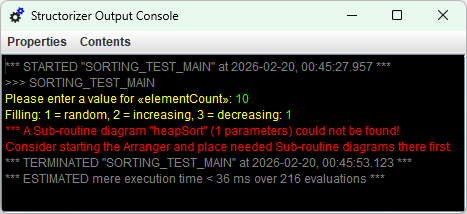
If custom subroutines are executed as top-level diagrams for debugging purposes then the Executor will simulate the call by asking the user for the value of every argument (as if there were input statements at the beginning) and will present the result value in a message box (or a scrollable list view, if the result value is an array or record).
6.4. Complex Data Types
Arrays
Structorizer supports the use of arrays, basically of one-dimensional arrays. Technically speaking, Structorizer does not offer multi-dimensional arrays. But if you place arrays into the elements of (one-dimensional) arrays then the behaviour comes near to some approximation of multi-dimensional arrays.
One-dimensional arrays may be introduced in two ways:
1. Element-wise assignment (incremental growth)
As soon as you write an assignment or input instruction and append square brackets with an index expression to the target variable name, the variable will be made an array variable (if it hasn't been already):
names[2] <- "Goofy"
INPUT x[0]
The index range of arrays starts with 0. If you assign something to an array element with larger index than used before, the array will automatically be widened up to the new index. If there are index gaps, then the in-between elements will be filled with 0, e.g. in the first example above, the resulting array names would be filled as follows: {0, 0, "Goofy"}. Note that a reading access with an index larger than the highest index used for assignments or input before will abort the execution with an error message.
Since version 3.32-25, it is even possible to create some multi-dimensional array-like conglomerates by initially assigning some value to a new variable with several indices (but be aware that the result will be some rather sparcely filled array of arrays where just the given index path is fully established):
matrix[3,2,4] <- 27.5
INPUT A[0][6]
In the first example above, the resulting nested array structure matrix will just be filled as follows: {{{}}, {{}}, {{}}, {{}, {}, {0, 0, 0, 27.5}}}.
2. List initialisation
You may initialise an array variable with a list of element values, enclosed in curly braces (like in C, Java etc.):
values <- {17, 23.4, -9, 13}
friends <- {"Peter", "Paul", "Mary"}
You may combine the initialisation with a declaration in one of several syntactic styles (Pascal or, since version 3.32-04, also Java/C#):
var values: array of int <- {17, 23.4, -9, 13}
string[] friends <- {"Peter", "Paul", "Mary"}
Version 3.24-10 introduced the opportunity to provide such an initialiser expression even in the text field of an input dialog (as popped up by an executed input instruction), this way making the input variable an array variable:
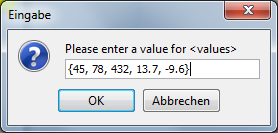
Actually, it is not necessary in Structorizer (though highly recommendable for the processing algorithms), that all elements of an array be of the same type.
Arrays may be passed as arguments to a subroutine (mechanism is call by reference, i.e. changes to the array content will be propagated to and seen by the calling algorithm, unless the argument is an initialiser or the parameter is declared const). Routines may also return arrays as result.
Arrays should not be put into the expression list of an output instruction. An element-wise output is recommended. (Even if Executor may cope with direct output of arrays, code export will usually not produce sensible code in this case.) If a subroutine executed at top-level returns an array, however, then the array contents will be presented in a scrollable list view. This allows separate testing of subroutines requiring some of their parameters to be an array (on top-level execution, parameter values are requested interactively, and the input of a value list in curly braces provides an array, see above) or returning an array. The same holds for record variables or expressions, by the way.
Array variables or braced value lists (aka array initialisation expressions) are the natural things to be used as collections in FOR loops of the TRAVERSING variety (FOR-IN loops), see the FOR loop User Guide page for details.
The following NSD shows some advanced examples of executable and exportable array operations:
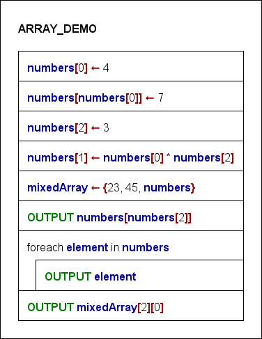
As already stated above, you may put entire arrays as elements into other arrays (see fifth instruction in the example diagram above, where one of the elements for mixedArray is the previously filled array named numbers; the second instruction, however, does not show nested arrays but instead the use of an index that has been taken out the same array, which seems somewhat bizarre but is sometimes used for indirection). Hence, it's possible to construct something resembling (though not actually being) a multi-dimensional array. The last instruction above shows the cascading index access to write an element of an inner array. From version 3.32-11 on, you may even write an index list between brackets to abbreviate the chained brackets, such that a[i,j] will be equivalent to a[i][j].
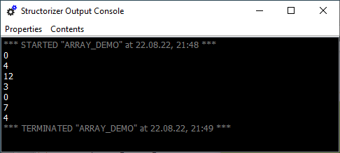
But be aware that Structorizer does not guarantee orthogonal multi-dimensional arrays, where all rows have the same number of columns etc. The "rows" may have different shapes of content, instead. So it is completely up to you to ensure that a combined index access makes sense and is structurally interpretable and correct.
In order to construct a surrogate for a small multi-dimensional array you may use a nested array initialisation expression, e.g.:
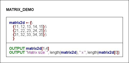
Then you can access each of the elements and query the length (element number) of an array no matter whether it's nested:

In no case, however, you may incrementally widen an outer array of a "multi-dimensional" conglomerate by attempting to assign a value to a (non-existing) element of a fictitious array at a higher index than already existing:
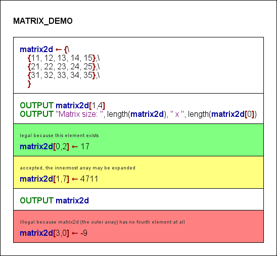
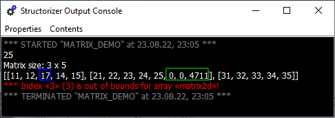
The last instruction tries to assign value -9 to element 0 of an array assumed to be placed in the non-existent row 3 of the outer array. To widen the outer array automatically would not even help because this does not create the required inner array there. What you would have to do is a two-step sequence in this case:
- Append a new sub-array to matrix2d, e.g.:
matrix2d[3] ← {41, 42, 43, 44, 45}
- Override the element in the interesting (and now existing) place:
matrix2d[3][0] ← -9
Strings
Strings are not handled as arrays in Structorizer. (Instead they behave like objects of Java class java.lang.String, because that is what they actually are.) That means: You may obtain the length of a string s either by applying the Java method length() to it — s.length() — or by using the built-in function length(s). Character access via index brackets is not supported. To access a character in a string s, you may either write s.charAt(i) where i counts from 0 to s.length()-1, or you may use the built-in function copy(s, i, 1), which in fact extracts a substring of length 1 (which is not the same as a character, though) at position i where i ranges from 1 to s.length(); you may also have a FOR-IN loop iterate over a string variable (where the loop variable will get actual characters):
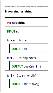
You may not replace a character within the string. You may only form new strings by using the built-in string functions (see reference above) or by concatenating strings with operator +.
Records / Structs
Since release 3.27, Structorizer also supports the use of records (aka structs). Like arrays, records are complex data structures offering the possibility to combine different data within one variable. Unlike arrays, records have named components, which may explicitly be of different data types. Think of a date of the Gregorian calendar, consisting of a year, a month, and a day number. You might use an array of three numbers in a fixed order for it, but it would be more expressive to access the components via names. The component names and types, of course, must be declared to allow an unambiguous access. Likewise, you might want to combine data about persons, say their name, height, sex, and — hey! — their date of birth. So you should be able to build records on other kinds of records and to give these constructs a unique name.
A type definition syntax was introduced therefore.
Type definitions are to be placed within ordinary elements of Instruction kind, though a type definition doesn't do anything except telling Structorizer how variables of that kind are structured from that element on. The type definition for a record/struct type describes the structure and introduces a user-chosen name for these constructs:
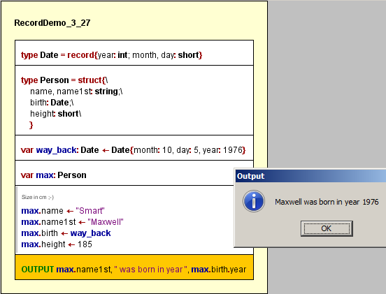
The first two elements show record type definitions. Each starts with the keyword type, then the name for the type is to be specified, followed by an equality sign and one of the equivalent keywords record or struct and the component declarations within curly braces. Each component must be given a name and should be given a type. The third element of the diagram shows a record variable declaration with initialization via a "record literal" (or say an initialization expression). The initializer looks similar to the type specifications but starts with the previously defined type name instead of struct or record. Instead of component type names now appropriate values must be associated to the field names. The order of the fields may be arbitrary.
The fourth element of the diagram screenshot shows a mere declaration (without initialization), whereas separate component assignments to the otherwise uninitialized variable max follow in the fifth instruction element.
From version 3.32-11 on, the element editor supports you with component name suggestions whenever you type a dot after a (possibly complex) variable for which Structorizer infers a record structure from the type definitions and preceding declarations:
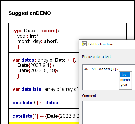
You may easily select one of the component names from the pulldown list and insert it into the text area by pressing the <Enter> key.
Since version 3.28-06, "smart" record initializers are supported, the item list of which may contain mere expressions — provided their order corresponds to that of the component declarations in the related record type definition. So variable way_back might also have been initialized as shown by the green instruction in the modified diagram snippet below:

From the first explicitly occurring component name, however, parsing will ignore all remaining values without component name prefix, such that in the example of the red instruction only components year and month of record partial would be assigned, whereas the value 21 will be ignored. (As the tooltip in the screenshot shows, Analyser will warn that the day component isn't going to be initialized.)
From version 3.32.12 on, Structorizer also supports type definitions for array types and alias type definitions:

If you pass variables of certain record type as parameters to a subroutine diagram, then a dilemma occurs: Where to place the type definition, such that the parameter structure would be available in both diagrams? In this case, the type definition can only be placed in an Includable diagram, which is then to be included by both the caller and the called diagram.
Enumerators (versions ≥ 3.30-03)
Often you are confronted with a type of data that is to represent one out of a finite and fix set of categories, e.g. the day of week (Monday / Tuesday / Wednesday / Thursday / Friday /Saturday / Sunday) or a university member status (Student / Assistant / Professor) or something the like. Of course you might code these values with integral numbers, but it would be more readable and intelligible if you could use symbolic designations. To use strings instead may be a bad option as it costs more memory and provides only poor options statically to ensure and check the correctness of such a value (e.g. against wrong spelling). Most programming languages therefore provide the concept of so called enumeration types. Actually, an enumeration type is no more than a set of named integer constants that is introduced by enumerating their identifiers.
You may define an enumeration type in Structorizer in the following way:

type and enum are reserved words, the identifier between type and = becomes the name of the enumeration type, the identifiers listed between the curly braces are the enumerator constants to be defined. Structorizer assigns consecutive integer codes to the enumerator elements in the listed order, i.e. the first name (e.g. Monday) will be associated with 0, the second one with 1, and so on.
If the coding matters in certain case, then you may explicitly assign a code value to some enumerator identifiers as shown in the orange element of the demo diagram below. The required operator symbol is = , the code must be a constant integer value (ideally a literal, like 42), but may be specified as a simple constant expression i.e. an arithmetic computation from integral constants (integer literals or previously defined constants, including enumerator identifiers) as shown below. Subsequent enumerator elements will be coded incrementally from the explicitly assigned element on.
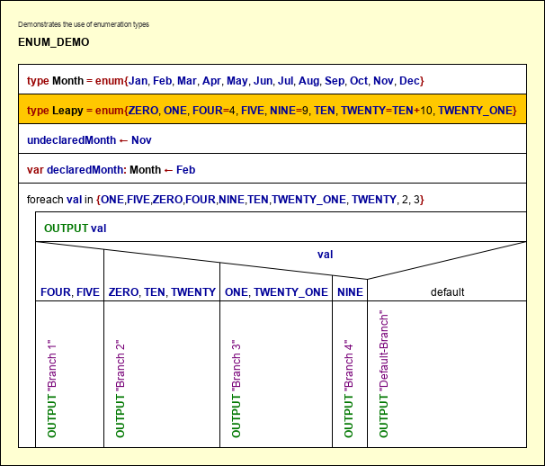
6.5. Special syntax for ARM
About the ARM Generator prototype

Since version 3.32-02, Structorizer provides (a somewhat premature) prototypical generator for ARM assembler code thanks to Alessandro Simonetta et al.
ARM (assembler) code is a mnemonic representation of machine code for ARM processors, such that the abstraction level differs fundamentally from that of higher-level programming languages like Pascal, C, Java, etc.
Two uses cases (or perspectives) may have to be distinguished here:
- ARM code generation from an arbitrary Nassi Shneiderman diagram. This would require a full compiler capability (possibly even breaking down floating point arithmetics to sequences of byte and word operations). This cannot be the task of Structorizer on this early stage.
- Conversion of algorithms formulated on the conceptional level of RISC processor capabilities from a structogram to ARM assembler code. In this perspective, it may not even be desirable to implement too much compiling intelligence here. Even conceding this, the conversion capabilities of this early prototype are still very limited. On the other hand, this required some additions that don't work or don't even make sense in e.g. Executor (e.g. address retrieval for a variable or direct memory access as if it were an array). These additions are briefly explained below.
From version 3.32-05 on, Structorizer follows a two-fold strategy to combine both intentions: On the one hand, a very restricting grammar check may be imposed via the Analyser Preferences, which complains about Element lines that leave the narrow ARM processor capabilities behind. Via a respective export option you may even have the ARM generator reject such rich instructions. On the other hand, the ARM generator will be enhanced to accept and compile more and more complex expressions and instructions in an evolutionary development process. To make use of these extending capabilities you should lift the just mentioned restrictive options. But please do not expect too much — you will simply have to check the generated code (in the code preview) to find out whether ARM generator coped or not.
Some important facts in a nutshell:
- The set of supported statements is very limited and the syntax may even differ from the Structorizer conventions (see Basic Concepts).
- Certain variable names will be interpreted directly as machine registers, and there are some addtional keywords or markers for certain machine-oriented aspects.
- Array definitions differ somewhat from the usual conventions in Structorizer (see Arrays).
- Records and Enumerations are not supported at all in this context by now.
- Strings can only be used in variable assignments (better: initialisations), in order to create an array of characters in the "memory".
- The generated code for an intended array access via a copy of a variable or register that was associated with the address of an array or string should not be expected to make sense.
Register mapping
Variable names R0, R1, etc. through R15 and, equivalenty(!), r0, r1, ..., r15 are interpreted as registers of the ARM processor architecture. Other variables will be mapped to registers not explicitly referenced. Register name R15 (or r15) denotes the program counter and may only be used within a condition (comparison expression) but may not be set explicitly or used in other kinds of expression.
If more than 15 variables occur in a diagram then the ARM generator will refuse to translate them sensibly (in future it is meant to do a more or less intelligent management in memory). If both the upper-case and the lower case register name of the same register (same number) occur in one diagram (e.g. R5 and r5), then the behaviour is undefined.
<identifierR> thus denotes an identifier as described in Basic Categories where ARM register names are treated in a special way.
<register> denotes one of the register names R0, R1, ..., R14, or r0, r1, ..., r14.
Expression complexity
The manageable complexity of expressions is very low at the moment. Only "flat" expressions using one kind of operator (e.g. addition or multiplication, not both) can usually be processed, no complex nesting is supported, parentheses will be ignored.
Next to the usual assignment operators, the only supported operator symbols (referred to as <operator> below) are:
+, -, *, &, |, and, &&, or, ||
Logical expressions (to be used in Alternatives, While and Repeat loops) may either be atomic or a series of one or more comparisons combined either by and (equivalently: && ) or by or (equivalently: || ), but not both. Do not rely on operator precedence, parentheses will internally be eliminated. Atomic logical expressions may be variables or registers (which are then implicitly tested to be non-0), a negation operator (not or !) may be applied. Note: In comparisons the left operand must always be a register or variable (such that e.g. 4 < R5 is not allowed, whereas R5 > 4 is).
Examples:
- isNice
- not R5
- R4 < 17
- R0 = 'b' or R1 >= R4 or R6 = 0x2e4
To keep things simple, we will introduce a combined literal concept <int_literal> here, which is either an integral decimal <literal_int> or a hexadecimal literal <literal_hex> (see Basic Concepts):
<int_literal> ::= <literal_int> | <literal_hex>
Statements
Basic assignment
The basic assignments allow just Boolean literals, integral literals, variables or a single operation between two simple terms.
<identifierR> ( <- | := ) (true | false)
<identifierR> ( <- | := ) ( <identifierR> | <int_literal> ) [ <operator> ( <identifierR> | <int_literal> ) ]
Examples:
- test ← false
- count ← R3
- R4 ← 0x6 + count
Memory read and memory write operations
This is an alternative way to access the content of a declared and intialized array (by version 3.32-03, other variables are not allocated in memory but rather mapped to registers).
<identifierR> ( <- | := ) (memory | memoria) '[' <identifierR> [ + <int_literal> ] ']'
(memory | memoria) '[' <identifierR> [ + <int_literal> ] ']' ( <- | := ) <identifierR>
Note: The <identifierR> within the brackets may be a variable name or a register name, depending on how the array was declared (see Array support below). The given <int_literal> must be the actual address offset rather than an index: No automatic index transformation will be performed.
Examples:
- R6 ← memoria[height]
- R2 ← memory[R3 + 0x12]
- memory[R3] ← R8
- memoria[count + 4] ← r2
Address assignment
Assigns the address of some variable held in storage (i.e. an array) to a register. The right-hand side of the assignment resembles the call of a built-in function in syntax. The argument must not be a register name (if the array was declared with a register name then the address assignment will have been done automatically).
<register> ( <- | := ) (address | indirizzo) '(' <identifier> ')'
Examples:
- R5 ← address(storage)
- R2 ← indirizzo(count)
Character assignment and String initialization
Assigns a character or string literal:
<identifierR> ( <- | := ) " <character>{<character>} "
<identifierR> ( <- | := ) ' <character> '
Examples:
- digit ← '3'
- R9 ← "These are 4 silly words"
Remarks:
- A string literal must not be empty!
- A string initialization induces the memory allocation of an array of the contained characters, each represented by an entire ARM word (4 Bytes), which is sufficient for UTF-32.
- A character literal assignment, in contrast, is converted into an instruction loading the charcter code as a direct operand into the target register.
- A string cannot be prolongated in ARM code therefore (as the memory reservation will exactly follow the length of the string literal). So the export of diagrams that use e.g. string concatenation will fail to produce usable ARM code.
- Since version 3.32-04, character assignments require single quotes (') as delimiters of the character literal. String initializations, however, require the string literal to be delimited with double quotes (").
- There will not be a terminating '\0' character at the end of the allocated string unless you switch on an ARM-specific export option "Store strings with 0-termination".
- Non-Ascii and control characters will be expressed by their hexadecimal code point value in the exported code.
Array support
Arrays are first to be initialized by a statement of the following form, which may or may not involve a declaration over a specific low-level data type (since version 3.32-04, the type description is required to be similar to C# or Java, i.e. an empty pair of brackets must follow to the element type name):
[(byte | hword | word | quad | octa)'['']'] <identifierR> ( <- | := ) '{' <int_literal> { , <int_literal> } '}'
If none of the types "byte[]", "hword[]", etc. is specified then "word[]" will be assumed, which designates a 32 bit value (4 byte width). Note that since version 3.32-03 an ARM-specific export option controls whether memory alignment to entire word addresses will automatically be performed.
Example: word[] array1 ← {56, 7, 98}
If <identifierR> designates a register, then the register will automatically be associated with the address of the array, whereas the array itself will be placed with a not directly accessible generic label.
Then assignments of the subsequent kinds are meant to be accepted:
Read from an array:
<identifierR> ( <- | := ) <identifierR> '[' (<identifierR> | <int_literal>) ']'
Example: c ← array1[R5]
Write to an array:
<identifierR> '[' (<identifierR> | <int_literal>) [ + (<identifierR> | <int_literal>) ] ']' ( <- | := ) <identifierR>
Example: array1[R2 + 7] ← R4
Remarks:
- Be aware that by now an array element access still cannot be exported to ARM code if placed within other kinds of instruction or expression, e.g. if you want to compare the content of an array element you must first assign it to some variable or register and then compare this.
- Value lists in traversing FOR loops (collection-controlled loops, FOR IN loops) may either be explicit (array literal or comma-separated list over integer literals) or variables / registers that refer to a declared array of integers in order to allow successful export.
The export of input and output instructions is only supported if the GNU syntax mode is chosen in the ARM-specific export options. Input instructions require all their parameters to be simple variables (or registers), i.e., no array element access or record component access is syntactically supported. The expression list of an output instruction may comprise variable/register names and integer literals. Whereas in the restrictive grammar check of the ARM instruction level approach (see use case 2 above) complains if there is no item in the instruction or if the input instruction contains a prompt string literal, the generator will tolerate them, a prompt string in input instructions is ignored.
<input_keyword> <identifierR> { , <identifierR> }
<output_keyword> ( <identifierR> | <int_literal> ) { , ( <identifierR> | <int_literal> ) }
Examples:
- INPUT R3, number
- OUPUT number, -21, R3
ARM assembler instructions
Moreover, all instruction lines that start with one of the following ARM assembler mnemonics (case-ignorantly) are considered as ready-to-use ARM instructions (without further syntax analysis, only variable names will be replaced by register names and unprefixed integer literals will be prefixed with '#'):
add, adc, adcs, and, asr, b, bic, bkpt, cdc, cdp, clz, cmn, cmp, cpsid, cpsie, cpy, eor, ldc, ldm, ldr, lsl, lsr, mcr, mla, mov, mrc, mrrc, mrs, msr, mul, orr, pkhbt, pkhtb, rev, rfe, ror, rrx, rsb, rsc, sel, setend, sbc, smla, smlsd, smmla, smmls, smuadx, srs, ssat, stc, stm, str, sub, swi, sxtab, sxtah, sxtb, sxth, teq, tst, usat, uxtab, uxtah, uxtb, uxth.
Consequences of ARM syntax limitations
The following screenshot shows the consequences of the syntax limitations. The restrictive syntax check complains about the input instruction with prompt string, whereas the code preview demonstrates that ARM generator actually copes with it. It produces more efficient code than from sequences of single input/output elements, by the way since repeated assignments to the address register can be omitted:
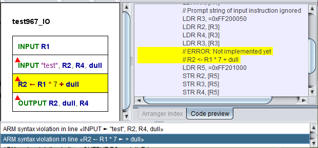
The above complained assignment expression with two operators can still not be converted, indeed.
7. Features
Beyond being a mere NSD editor, Structorizer offers you several goodies to make more of the creation of Nassi-Shneiderman diagrams than just an unliked duty to document algorithms. It may really be something enjoyable as you will find out. Structorizer particularly addresses the need of beginners rapidly to achieve reassuring results.
- A highlighting feature shows detected variables, operators, certain configurable keywords, and text literals in bold style and/or certain colours.
- A configurable static Analyser component continuously lists probable syntactical or logical flaws and allows to find the inducing element.
- Executor: You can run diagrams, execute them in step mode or set breakpoints to test and debug the algorithms. Diagrams may call other diagrams as sub-routines.
- Turtleizer is a drawing canvas where you may have a symbolic tortoise draw lines and figures controlled by some simple instructions.
- Runtime Analysis: A mighty feature within the Executor to visualise code coverage on testing, element execution counts, loads of basic operations to compute an algorithm or some parts of them, also allowing count-down breakpoints.
- File I/O API is a syntax entension allowing you to create, read, and modify text files by executing a diagram. The File I/O API instructions are executable and exportable. Working with structured and binary files is not supported, however.
- Code generators: You may export your algorithms into several established programming or shell languages (requiring some manual postprocessing, of course).
- Code parsers: You may import source files of some programming languages (currently: Pascal, C, COBOL, Java, and Processing) in order to present their contained algorithms as Nassi-Shneiderman diagrams.
- Arranger: An enlargeable and zoomable canvas where several diagrams may be arranged side by side or parked as a kind of subroutine pool. This allows you to create multi-diagram picture files or to watch the execution of different subroutines of a running program NSD. It also allows you to store related diagrams together with their arrangement.
- Find & Replace is a text search and substitution tool dedicated for sets of diagrams, offering regular expression support, and thus allowing to perform complex and consistent semi-automatic editing processes.
- The Content Assist accelerates and facilitates the editing of the element content by context-sensitive autocompletion suggestions for entered words.
- The Translator invites the user community to contribute to the maintenance of Structorizer: it's a tool to facilitate the efforts of localization (i.e. the GUI translation into more and more user languages). It also allows to individualize the labels and messages of the Structorizer GUI.
See the details by inspecting the respective subsections.
7.1. Code generator
Structorizer allows you to convert your designed algorithm to several programming languages (among them Pascal/Delphi, Java, C, C++, C#, BASIC, Python and even some script and shell languages) as well as several LATEX and flowchart formats.
Note that all interactive code export opportunities (including Live Code Preview) will be disabled (even missing in the user interface) if a central predominant ini file is used which contains a line "noExportImport=1" (versions ≥ 3.30-11). This line can only be inserted manually, its position does not matter.
Code export to file
To generate source files, select the respective menu item of submenu "File › Export › Code". See Export Code for more details and Export Options for possible generator configuration items.
In most cases, however, you may not expect a flawless and instantly compilable or executable code. This wouldn't be feasible because a (more or less syntax-free) Nassi-Shneiderman diagram will usually not specify all details a specific language might require.
What you yet will obtain is an almost correct algorithmic skeleton that will have to be post-processed a bit manually to achieve a working program or routine. Typically, variable declarations will have to be provided, for instance. Or some algorithmic features like exit Jumps or PARALLEL sections may not be supported by the target language. "TODO" comments placed in the code will help the beginner in perceiving what is to be done to accomplish the output. Despite the incompleteness code export will already help the programming beginner a lot. And even experienced programmers who want to document their algorithms are spared a great deal of duplicate work if they start with Structorizer and then just export and adaptate the designed algorithm.
Please be aware that for some languages there is a plenty of dialects out there. So it's not unlikely that the derived code may work with one system but cause errors with another. (However, if you think that the exported code serves too exotic a dialect and should better be replaced by a more compatible output, just contact the Structorizer team, please, and raise an issue, ideally giving a reference to the respective programming language specification or documentation. Possibly, some additional export options might be introduced to address diverging demands.)
Live Code Preview
Since release 3.30, you may directly watch the effects of your editing the diagram on the code that would be exported into your favourite programming language.
The code preview is enabled via menu "View › Show Code preview?" (versions ≤ 3.32-13: "Diagram › Show Code preview?"):
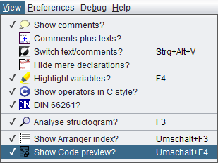
The Code Preview shares a tabbed pane with the Arranger Index in the right part of the Structorizer main window:
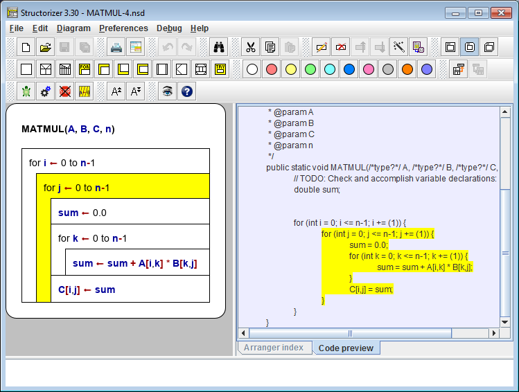
The target language of the code preview is the one configured as "Favorite Code Export" in the Export Options:
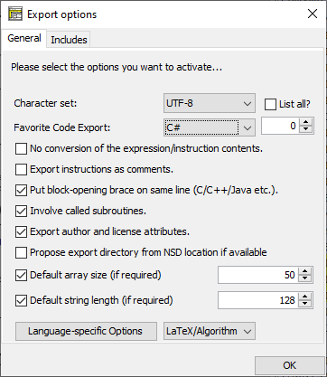
(As outlined in Export Options, it also determines the menu item "File › Export as ...".)
The Code Preview content is updated whenever you modify the diagram, and as soon as you select an element or a range of elements in the diagram then the corresponding code passages (line range) will simultaneously be highlighted and scrolled to as well.
Conversely, when you click on a code line in the preview window then the corrsponding element in the diagram will be selected and the entire code line range derived from it will be highlighted. A double-click in the Code Preview even opens the editor for the associated element.
You may not enter or modify text in the Code Preview directly, however.
(With certain export languages some elements (like mere declarations) may not directly correspond to a continuous sequence of lines in the exported code or e.g. the introduction of a variable may require declarations or initializations in languages like Pascal or pure C at different locations in the code. In these cases, the simultaneous highlighting may fail or apply only to the closest resulting lines.)
The context menu in the Code Preview allows you easily to change the favorite export language without having to open the Export Options dialog (which will be synchronised, of course). In addition, you may launch the code export here conveniently and switch off the Code Preview:
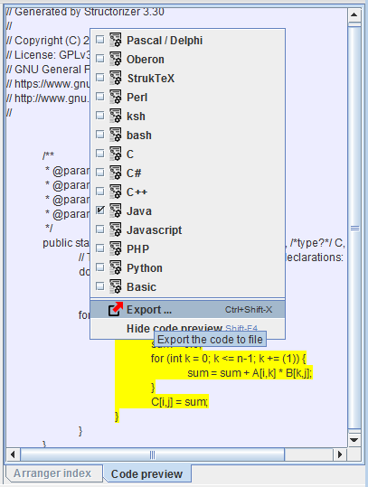
If you keep the Code Preview enabled while you debug your diagram (with Executor) then the orange execution highlighting will simultaneously wander through the Code Preview as well:
(In order to accelerate execution slightly, particularly if done with minimum delay, it is recommendable, however, to hide both Code Preview and Arranger Index during execution.)
7.2. Syntax highlighting
Generally, all text in the diagram is written in standard font (black), but you may enable the option "Highlight variables?" in the menu "View" (before version 3.32-13: "Diagram").
The name "Variable highlighting" doesn't quite exactly describe what this feature is doing, because it's not only variables that are emphasized. With this option enabled, Structorizer helps you to distinguish different syntactic categories and easier to keep an overview by highlighting certain names or literals in the instruction texts.
These are:
- variables — bold dark blue
- operators — bold burgundy
- input / output keywords — bold green
- string literals — violet
- jump keywords — bold apricot
- alias names for controller routines — underlined
In addition, certain symbols are shown in a more user-friendly way. These are:
Symbol conversion
| Character sequence |
Presented symbol |
Meaning |
| <- |
← |
Assignment symbol |
| <> |
≠ |
Comparison operator |
| != |
≠ |
Comparison operator |
| <= |
≤ |
Comparison operator |
| >= |
≥ |
Comparison operator |
Besides optically structuring text, this highlighting may also give helpful indications of syntactical flaws that might cause trouble on execution or code export.
Syntax highlighting makes only sense, of course, if you intend to fill in the diagram elements with nearly executable code. If you just write some comment-like plain text, pseudocode, or e.g. shell code (which is syntactically incompatible with HLL conventions) you will prefer to switch off this highlighting mode (see Highlight variables?).
7.3. Analyser (static)
The Analyser may statically check the current diagram for certain syntactical and structural deficiencies. Which ones of the available checks are to be performed is configurable (see below). The analysis is done at live time (i.e. during editing) and reports detected potential problems in the report area below the diagram work area.
To enable or disable the static Analyser as a whole you may use menu item "View › Analyse structogram?" or simply press <F3> (see Settings > Analyse structogram?). In the Analyser Preferences you may opt in or out any of the individual rules available for the analysis. You may also opt out the placing of little marker triangles in elements with associated warnings or hints as introduced with version 3.30-14 (see examples in the screenshots below). Consult Analyser Preferences for a list and a short explanation of the rules.
The analyser report area is only visible while the Analyser is enabled. (During execution the static analyser will be temporarily disabled.) Simply drag the horizontal separating border up or down to tune the display ratio between the work area and the report list. (If you don't see the report area even though you had enabled Analyser then try cautiously to drag the bottom border of the diagram area upwards into the Structorizer work ara. In contrast, there are very rare cases that Structorizer may start with the report area occupying the entire place below the toolbar — then drag the upper border of the report area down to give the work area its share.)
When you see warnings in the report area, just click on one of the report lines to select and highlight the corresponding element in the diagram. If you double-click on a report line, this will even open the editor for the related diagram element.
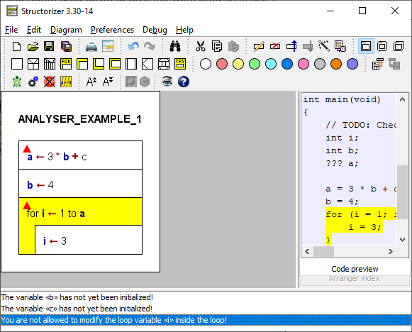
In the above example, you see three detected problems in the Analyser report area (the bottom section). The causing elements are additionally marked with red triangles (a new optional feature introduced with version 3.30-14, see Analyser Preferences). From version 3.31-05 on, you may raise a tooltip showing all warning messages related to the element by having the mouse hovering over such a triangle:
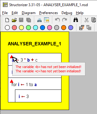
The first two of the messages refer to instruction 1: In the expression, variable b is used, but its initialization hasn't been performed yet, it's following in an instruction executed later. For identifier c in the same expression no initialization at all could be found anywhere (c is not bold in the diagram, therefore). The responsible rule for this kind of analysis is "Check for non-initialized variables". This rule also checks for variables the initialization of which may not necessarily be reached, e.g. because it is placed in a branch of an Alternative or whithin a loop. Such cases are reported with a slightly differing message.
The third of the messages relates to the body of the FOR loop where a manipulation of the control variable i is tried, which is usally regarded as illegal (though some programming languages like C or Java allow such questionable ways to control the loop, e.g. to leave it prematurely; you may even frequently see them used). The responsible Analyser rule is "Check for modified loop variable".
Likewise, loops where the body has no obvious influence on the loop condition (such that an accidential endless loop may be supposed) may be detected via a different rule etc.
(As mentioned above, see Analyser Preferences for a list of available rules.)
Of course, you may neither rely on a "complete" analysis nor should you be sure that all messages are correct, i.e. there may be "false positives", since a structogram may neither be expected to adhere to strict syntactic rules nor is it possible at all to decide certain semantic properties of an algorithm algorithmically. (The undecidability of many interesting algorithm properties is proven!)
Since version 3.30-15, the report list will automatically scroll to the first warning that is related to the element you just selected. More precisely, it will ensure that the first related warning gets visible in the report list viewport (this does not necessarily mean it will be the first line in the viewport).
If a collapsed element shows an Analyser marker then the respective tooltip (see above, since version 3.31-05) will list the problems of all contained elements after a short description of the causing element:
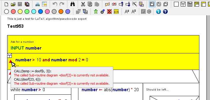
Since version 3.24-15, Analyser will place an element-independent warning at the top of the Report List while mode Switch text/comments is active:
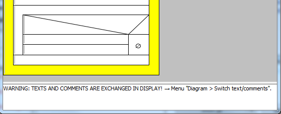
Note: Besides static analysis you may also perform runtime analysis, which is a separate feature of the Executor.
Since release 3.27, the Analyser Report List is also used to guide beginners through the creation and use of some simple diagrams:
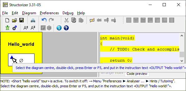
When you let the mouse hover over a marker triangle (see above), related tutorial hint messages in the tooltip will appear in blue colour as well, such that they can easily be told from warnings (version ≥ 3.31-05 only).
For more details see Guided Tours / Tutoring.
7.4. Turtleizer
The Turtleizer component allows you to move a small green turtle over a drawing canvas and let it draw something. On execution start, the background is white, the default pen colour is black, the pen is down and the turtle is visible and placed in the centre of the Turtleizer canvas (which has a default size of about 500 x 500 pixels).
API
You can use the following instructions (note that the type specifiers int and double only declare what number type the arguments are expected in or coerced to, the type specifiers are not to be inserted into the instructions, of course):
|
forward(double nPixels)
fd(int nPixels)
|
Make the turtle move nPixels pixels forward, drawing a line segment if pen is down. (fd is a low-precision version of forward, see notes below.)
|
|
backward(double nPixels)
bk(int nPixels)
|
Make the turtle move nPixels pixels backward, drawing a line segment if pen is down. (bk is a low-precision version of backward, see notes below.) |
|
right(double angle)
rr(double angle)
|
Rotates the turtle to the right by some angle (in degrees!).
|
|
left(double angle)
rl(double angle)
|
Rotates the turtle to the left by some angle (in degrees!).
|
|
gotoXY(int X, int Y)
gotoX(int X)
gotoY(int Y)
|
Sets the turtle to the position (X,Y).
Sets the X coordinate of the turtle's position to a new value.
Sets the Y coordinate of the turtle's position to a new value.
|
|
penUp()
|
The turtle lifts the pen up, so when moving no line will be drawn.
|
|
penDown()
|
The turtle sets the pen down, so a line is being drawn when moving.
|
hideTurtle()
|
Hides the turtle. |
| showTurtle() |
Show the turtle again. |
| setPenColor(int red, int green, int blue) |
Set the default pen colour to the given RGB value (range 0...255 per argument). This colour is used by undyed move commands. |
| setBackground(int red, int green, int blue) |
Set the background colour to the given RGB value (range 0...255 per argument). |
| clear() |
Wipe the canvas from all traces of the turtle (without changing its remaining status; versions > 3.28-06 only). |
Three functions are available to retrieve the current position and orientation of the turtle (since release 3.27):
|
double getX()
|
Returns the current horizontal position (may be between pixels).
|
|
double getY()
|
Returns the current vertical position (may be between pixels).
|
|
double getOrientation()
|
Returns the current turtle orientiation in degrees (in degrees, range -180...180).
|
Since version 3.27-05 you have the opportunity to address the Turtleizer routines under individually configurable alias names. You may specify and activate your favourite aliases via menu Preferences › Controller Aliases ....
Please note that:
- Procedures fd and bk are not exact synonyms for forward and backward, respectively, but snap to an integral pixel model, which seems sound at first glance but is less precise than the internal floating-point coordinate model addressed by forward and backward, and even somewhat inconsistent. Remember that e.g. a walk to the next neighbouring pixel in diagonal direction hasn't a length of 1 pixel but √2. Hence, going a way of integral length in an awkward angle is not supposed to end at an exact pixel position. Whereas forward and backward will preserve the resulting floating-point coordinate, using fd and bk coerces the Turtle position to the closed integral pixel position. Only axis-parallel moves will definitely have exact integral length. With consecutive traversal moves, coercion differences < 1 pixel may sum up to enormous deviations on complex drawings, particularly with a large share of short moves. With a floating-point coordinate model, in contrast, the virtual position is not necessarily at an exact pixel position but consistent to the previous moving directions and lengths, which is important for the moves to come. Having both models available in Turtleizer, you may study the differences. (Via the menu items Edit ›
 To fine graphics and Edit ›
  To integer graphics you may convert selected parts of your diagram code from the one paradigm to the other and vice versa.) Be always aware that any call of fd, bk, or one of the goto* procedures will coerce the respective target position to an integral pixel coordinate, also as starting point for subsequent floating-point moves.
- The default pen colour for forward/backward/fd/bk commands is black. If you want the turtle to draw a coloured line segment, just colourise the respective element inside the diagram. Alternatively, you may set the default pen colour to a different RGB value, using setPenColor(r, g, b). All forward/backward/fd/bk commands in undyed (i.e. white) diagram elements will then use the most recently set default colour, whereas the instructions of this kind in colourised elements will still draw segments in their respective element colour. Hint: In oder to draw a white line (e.g. on a dark background) you cannot simply use a white (undyed) instruction element, but it will work to set the default pen colour as follows before: setPenColor(255,255,255).
- Negative values for pixel numbers and angles are allowed and will be equivalent to the corresponding positive value in the inverse procedure call, i.e. right(-angle) = left(angle) , forward(-nPixels) = backward(nPixels), and vice versa.
Negative argument values in setPenColour or setBackground will simply be replaced by their absolute amount.
- Omitted arguments are interpreted as 0.
- The calls of the built-in procedures listed above must not be placed in Call elements but ordinary Instruction elements.
- The goto procedures (gotoX, gotoY, gotoXY) will never draw anything — no matter whether pen is up or down. Don't forget that the coordinate origin of drawing canvases is the upper left corner and Y coordinates grow downwards.
- The background colour imposed by procedure setBackground will last till the next setBackground call, though starting a new diagram via the debugger resets the background colour to the default white.
- The angle returned by getOrientation() is 0 if the turtle looks upwards (north), it is positive while the turtle looks to the right (clockwise) and negative while the turtle is turned left (counter-clockwise).
In order to execute an algorithm containing some of the Turtleizer procedures listed above you must have pressed the button  to open the Turtleizer window first. This will automatically open the Executor Control panel as well. While the Turtleizer window is open it will then be sufficient just to invoke the Executor Control panel via button
  for another start. Without the Turtleizer window having been opened, the Turtleizer procedures won't be recognised and will cause errors on execution attempt.
Whenever the Turtleizer window is (re-)opened, i.e. the  button gets pressed again, the canvas will be wiped and a new turtle home position will be set in the centre of the window (whatever its previous dimension was). Since the zoom factor is not reset by reopening, the new home coordinates will consider the zoom factor. This home position will persist as start coordinate for any subsequent turtle diagram execution during the session unless you close/reopen the Turtleizer window.
If the Turtleizer window is closed after having been open before, Turtleizer procedures will not cause errors but the drawing will be done in vain, because the Turtleizer window will not automatically open and on reopening it, the content will be wiped.
The turtle can walk through negative coordinate ranges (.i.e., above the upper border or left of the left border) but its wake will not be visible there (neither will the turtle itself unless it returns to the positive quadrant), though from version 3.30-12 on you have the opportunity to move the drawing result into the visible quadrant via the Turtleizer GUI (see Context menu — displacement handling).
Example
The following algorithm draws a little hut with base hight and width from input with a triangular roof (having a right angle at top):
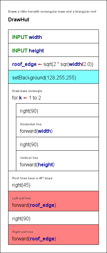
The drawn image with width = 200 and height = 100:
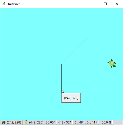
Note that the instruction "setBackground(128,255,255)", which is responsible for the cyan canvas colour, achieves this via the RGB arguments 128, 255, 255 only, the element colour has no effect here and was merely applied for illustration purposes. The red colour of the roof lines, however, is due to the dye of the last two "forward" elements.
Diagram code change helper ( ,
, )
)
If you want to study the consequences of the pixel coercions with an integral coordinate model in comparison to the floating-point coordinate model or if you happened to use the brief command names in earlier diagrams but want to change to the floating-point model, then the two menu items  and
and  in the Structorizer "Edit" menu will help you:
 To fine graphics replaces all occurrences of the Turtleizer procedures fd and bk within the selected element range by forward and backward, respectively;
 To integer graphics does it the other way round (i.e. replaces forward with fd and backward with bk).
If you have selected a structured element, say a loop, then all directly and indirectly contained instructions are involved, but not so instructions in called subroutines. In order to convert all instructions of the entire diagram at once, simply select the framing program or routine element. These instruction replacements are fully undoable and redoable.
A preliminary check whether the selection contains any relevant Turtleizer instructions at all is done to prevent you from inducing void undo or redo entries. After the conversion, a message box will pop up, telling you how many replacements were done.
Turtleizer GUI (versions ≥ 3.30-12)
Since version 3.30-12, the Turtleizer window offers several useful interactive features:
- Scrollbars allow to scroll over the entire drawing.
- A status bar (by default enabled) shows current information at the bottom.
- A context menu offers navigation, zooming, displacement, view settings, and export.
- Key bindings also allow to zoom, scroll, export, or tune the appearance.
- A popup shows the turtle world coordinates under the mouse position (versions ≥ 3.30-13).
- On dragging the mouse, you can measure the dragged line (versions ≥ 3.30-13).
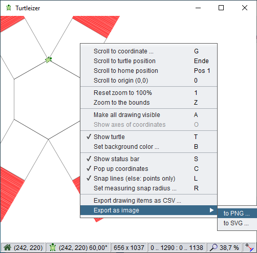
Status bar
The status bar (see screenshot above) presents the following information, from left to right:
- Home position of the turtle (pixel coordinates);
- Current turtle position and orientation (pixel coordinates and angle from North clockwise in degrees);
- Extent of the reachable part of the drawing (width x height) in pixels, i.e. hidden parts of the drawing in negative coordinate areas are not included;
- Current coordinate ranges (xmin..xmax : ymin..ymax) of the scrolling viewport;
- Zoom factor (in percent);
- Snap mode indicator for measuring function:
 for snapping to lines,
  for snapping to points (see measuring).
Tooltips help to describe the respective contents.
Context menu — navigation
Via the context menu, you can go (i.e. set the croll view) to the following locations:
- a user-specified coordinate (to be entered via a popping-up coordinate dialog);
- the current turtle position;
- the turtle home position
- before a drawing algorithm has been executed, current turtle position and home position will be identical,
- after having moved a displaced drawing into the visible coordinate range, this function will show you the relative home location (with respect to the drawing);
- the coordinate origin, i.e. turtle world position (0, 0).
Turtleizer will centre the view around the specified position unless the target position is too close to one of the canvas margins. It is not possible to navigate to negative coordinate positions or to positions beyond the drawing extensions in positive coordinate direction.
Context menu — zooming support
It is possible to zoom in and out via the <+> and <-> keys of the number pad or by rolling the mouse wheel while keeping the <Ctrl> key held down as usual.
In addition, via the contex menu you may:
- reset the zoom factor to 100 % or
- zoom to the actually presentable part of the turtle drawing (i.e. the parts in the positive coordinate range); this will fit the drawing into the current viewport.
Be aware that the zoom factor will not be reset by starting a diagram execution.
Context menu — displacement handling
Your drawing did not quite fit into the positive quadrant, i.e. some line segments got placed beyond the left or upper border? Don't worry: Turtleizer now allows you automatically to readjust the whole picture into the canvas area afterwards:
- Menu item "Make all drawing visible" (or key <A>) will enlarge the canvas to enclose the entire drawing, i.e. also all line segments drawn in negative coordinate ranges. (Note that this adjustment is not undoable. But the next drawing will again find a mere positive coordinate range.)
- After having extended the canvas around your picture this way, you may display a dashed lightred axes cross in order to mark the coordinate origin (0, 0). Use toggle menu item "Show axes of coordinates" or key <O> for it:
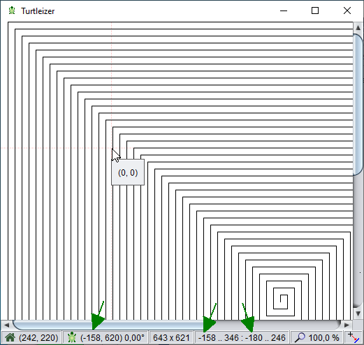
(In the above figure, the cursor indicates the axes crossing. Also note the negative coordinates in the status bar, being marked by the arrows.)
If the drawing does not have any parts outside the positive canvas range then these menu items will simply be disabled.
Context menu — view and measuring settings
The context menu allows you to:
- toggle the turtle visibility (alternatively to the hideTurtle() / showTurtle() calls in the executed diagram);
- specify the background colour of the Turtleizer canvas (alternatively to the setBackgoundColor() calls in the executed diagram) — this menu item will pop up a colour chooser dialog as shown in section Preferences › Colors;
- toggle the status bar visibility (by default the status bar is enabled);
- switch on or off the tooltip popup that shows the canvas coordinate at the current mouse position (versions ≥ 3.30-13, by default enabled);
- switch the measuring mode among snapping to nearest line (status bar icon
 ) or snapping to nearest points only (status bar icon
  );
);
- specify the snap radius for the measuring function in a range from 5 pixels (the default) to 100 pixels:
Note that starting a diagram execution will always reset the canvas to white background colour, but will neither affect the turtle visibility nor the status bar visibility, the snap settings etc.
Context menu — content export
Apart from simply saving a screenshot, the drawing content may now directly be exported in several ways:
- as CSV (comma-separated values) file;
- as PNG image file;
- as SVG vector graphics file.
Be aware that CSV and SVG files will always cover the entire drawing, no matter if parts of it are out of reach for the Turtleizer canvas (because of being drawn in negative coordinate areas), whereas PNG export will contain exactly the part of the drawing that is present on the Turtleizer canvas (even including the turtle symbol and the axes of coordinates if they were visible during export).
An export to a CSV file will cover all line segments drawn by the turtle in CSV ("comma-separated values") format — one row per line segment. The first two columns ("xFrom", "yFrom") reflect the start coordinate of the line, the next two columns ("xTo", "yTo") convey the end point coordinates, the ffth column contains a hexadecimally coded alpha-RGB value. (The file will contain only visible line segments, no invisible moves.) The resulting file may be imported by a spreadsheet application like LibreOffice Calc or MS Excel (to name a few):
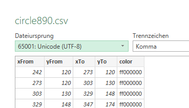
The file selection dialog allows you to choose your favourite column separator (since version 3.30-13):
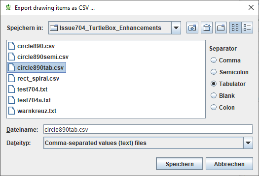
An export to PNG format will just save a copy of the Turtleizer canvas content as image file in original size (zoom factor being ignored). The clipped parts to the left and top of the upper left corner of the Turtleizer window will also be cut off in the PNG file. But you can of course do the "Make all drawing visible" step before — this will guarantee that the entire drawing be exported to the image file. On the other hand, the turtle itself will be part of the image if it is being shown in Turtleizer (you may hide it via the context menu or key <T>).
For SVG export, a coordinate offset will be applied that transforms the entire drawing into positive coordinate regions (even if you did not adjust the displacement as explained above), such that no parts will be missing (as for example the clipped top in the left screenshot, see elliptic orange mark). On the other hand, the size of the image will just equal the bounds of the drawing without space around it:
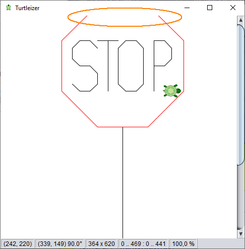 ==>
==> 
You may impose an integral scaling factor for the export (the zoom factor of the Turtleizer window is ignored here). Therefore a scale factor spinner is integrated into the file selection dialog, by default showing factor 1 (since version 3.30-13):
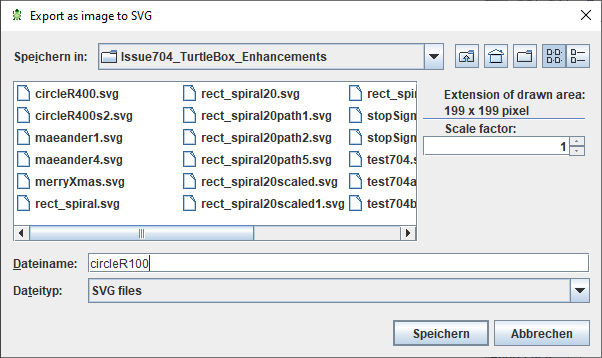
To specify a scale factor > 1 may make sense for very dense line patterns, which might visually degrade in original size after export. As SVG is a vector graphics format, the upscaling won't alter much but enlarges the default display size such that the resulting image may look better e.g. if directly presented in a browser. Look at the following case of a fret pattern drawn with a space of 1 pixel between lines (= line distance 2):

The SVG graphics exported with scale 1 looks bad in a browser:

The same turtle drawing exported as SVG graphics with scale 4 shows the precise pattern when displayed:

(The result of zooming the first SVG file display with factor 4 in the respective viewer will of course look identically, i.e., the default scale factor 1 does not induce an actual loss but may require scaling in the target context to achieve a satisfying effect.)
Measuring
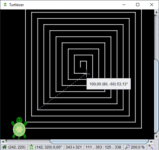
While you drag the mouse (with left mouse button pressed), the cursor will change to a cross hair shape (shown in the screenshot above), a dashed light-blue measuring line will be drawn, and a popup will present:
- the length of the line (in pixels),
- the pair of coordinate delta values (i.e. delta X, delta Y) in parentheses, and
- the orientation of the line (in degrees, clockwise from North, like the turtle orientation would be returned with getOrientation()).
The measuring line will automatically snap in to the nearest drawn lines (or start/end points only, depending on the current configuration) within the configured radius (5 pixels by default). The status bar indicates, which snapping mode is currently active (  or
or  ). You my alter the snap mode via key <L> or the respective menu item in the context menu.
If you keep the <Shift> button down while dragging then the measuring line will be coerced to strictly horizontal or vertical direction.
Turtleizer help
By pressing the <F1> key you will be shown this User Guide page in the browser. Using <Alt><F1>, the Turtleizer accelerator key bindings will be shown instead.
Aspects of code export
In exported code, the Turtleizer API will usually not work, of course, since the procedures and functions aren't native code in most target languages. Python, in contrast, contains a compatible module "turtle" (some necessary name conversions preserved), which is being addressed by the Python generator of Structorizer since version 3.28-10. For Java and C++ there are exactly compatible source packages available. See Export Source Code for details and links.
For other target languages you may happen to find some adaptable Turtle application or library in the wideness of the internet and manage to integrate it with your exported code. (Please let us know if you come across an easy-to-use compatible FOSS turtle module for some of the supported export languages.)
7.5. Executor
Preliminary Remarks
The executor is that part of Structorizer that tries to interpret and execute a diagram. It is available e.g. via the "Debug" menu:
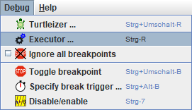
Please note, that Nassi-Shneiderman (NS) diagrams are designed to be free of any syntax. That means you may put arbitrary descriptive text into the elements. It depends on the level of detail, of course, how much sense that makes. Often it is more practical to use more formal notations like pseudo code or even more or less commonly accepted programming language constructs.
In order to "execute" an NS diagram, however, you have to stick to some kind of syntax. For the same reason, not all diagrams nor all contained structures can be interpreted. The executor was added to allow beginners to easily catch and understand control structures and execution flows. Over the time, however, several enhancements and accomplishments have made it a lot mightier than originally planned. You find an overview of the executable dialect used in Structorizer on the Syntax page of this user guide.
Overview of the remaining subsections of this manual page:
Launching Executor
To launch the executor, you may use the menu item "Debug › Executor ..." (see above) or click on the following toolbar icon:  . This will pop up the Executor Control panel (the functions of which will be described in section "Executor Control" further below):
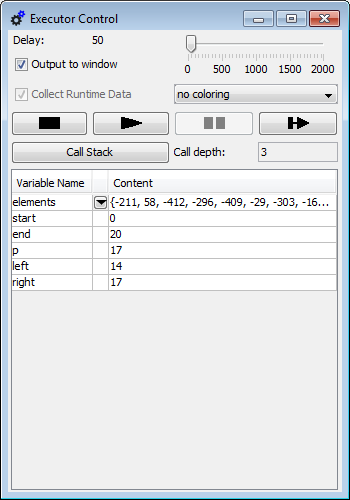
If your algorithm contains Turtleizer-specific subroutines, however, then you must click on the Turtle icon in the toolbar or select the menu item "Debug › Turtleizer ..." instead (unless the Turtleizer window has already been opened):  .
.
Note: You cannot close the control panel by the operating-system-typical close button (e.g. the top-right red 'X' in Windows, see image above, or the red traffic-light button in OS-X) while an execution is running or pending. Since release 3.27 you will be warned if you try.
The control panel will close automatically on execution termination unless Runtime Analysis is active. (From version 3.30-07 to 3.30-11 it remained always open but in practice this did not really work, see issue #829 for the reasons). You may close it by pressing the  button or iconize it in the usual way if it disturbs you in Runtime Analysis mode.
Executor Control
Here we explain the details of the Executor Control (opened e.g. via buttons  or
or  , as stated before). You see its layout in the figure above.
"Player" buttons
The most important controls are the four "player" buttons in the fourth row, having the following effect (from left to right):
 (Stop): Aborts execution immediately and closes the control window (unless Runtime Analysis is active), all execution status will be lost (tracked runtime counts will survive, though).
 (Run): Starts or resumes execution with the current instruction, running with the delay set via the slider in the first row.
 (Pause): Interrupts execution but retains current execution status such that, after some inspection and interaction, execution may be resumed.
 (Step): Just executes the current instruction and then automatically pauses before the next instruction or the end of the algorithm.
From version 3.30-14 on, the Pause button will temporarily be substituted by the following button while you pause on a CALL element (see CALL execution below):
 (Step into): Descends into the called subroutine diagram and continues the debugging within it (e.g. by stepping through it).
When having started with button Run, the execution will terminate in one of the following cases:
- The last instruction of the algorithm has been reached and executed.
- An EXIT element containing an exit instruction has been executed.
- An EXIT element containing a return instruction has been executed and the currently executed diagram is at top level.
- The Stop button has been pressed.
- A syntax or execution error has occurred.
The execution will pause (i.e. may be resumed) on one of the following events:
- Execution was carried out with the Step (or the Step into) button.
- The Pause or Step button was pressed during execution.
- A breakpoint is reached.
- An input instruction is executed and you pressed the "Cancel" button in the popped-up input dialog.
- An output instruction is executed (unless output mode is "output to window") and you pressed the "Pause" button in the popped-up display dialog.
- A subroutine CALL executed with Step over returned.
Some activities (like Call stack display) will only be enabled in paused state.
You resume execution via the Run or Step button (or the Step into button in case of a CALL element in versions ≥ 3.30-14).
Execution delay

With the slider in the top row you may control the execution delay between the instructions (for better observation). Whereas the mouse handling is rather rough, you may use cursor keys (left / right) to increment or decrement the delay value by 1 while the slider is selected. If you reduce the delay to 0 then some displayed information (like variable values, execution counts etc.) may not be updated unless the algorithm turns into paused state due to one of the events described above.
Output mode

The second row provides a checkbox "Output to window" allowing you to specify how output instructions are presented: If the checkbox is not selected then output instructions will pop up a message box showing the output value and having to be quit each time in order to resume, otherwise a console-like text window (see section "Output Console Window" below) will permanently be open into which all output will be written without pausing or waiting. Since the output is always logged to that console window (even while not being visible), you may still inspect the entire output history of the program by selecting the checkbox after having executed the algorithm with unselected checkbox. You may possibly have to open the Executor Control again to do so, because it usually closes after execution has terminated. Some examples are given in the section "Output Console Window" further below.
Runtime Analysis control

The third row provides a checkbox and a visualisation mode choicelist for Runtime Analysis. The checkbox on the left-hand side enables the tracking mode, the choicelist modifies the kind of element highlighting in dependency of the purpose of the analysis. The controls are partially disabled while execution is ongoing. See the Runtime Analysis page for details.
Call stack display

The fifth row shows you the current subroutine call level on the right-hand side: Every CALL instruction, which the execution dived into, increments the subroutine level by one, on returning from a called subroutine (and thus leaving the pending CALL element) the subroutine level is decremented. The top level (program level) is 0. Note that built-in functions or procedures do not affect the displayed subroutine level; only called Nassi-Shneiderman diagrams have an impact. In paused execution state, a click on the "Call Stack" button will pop up a scrollable list view showing the current content of the call stack (see section "Call Stack" below).
Variable display
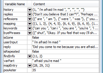
The lower region of the control panel is occupied by the variable display. As soon as a new variable is introduced, a new line will be added with the variable name in the left column and a string representation of its current value in the right column. In lines with a composed value (i.e. an array or record) the central column will show a pulldown button.
By the way: The three (and a half) ways to introduce a variable in Structorizer (the variables are named id1 through id5 in the examples) are these:
- as parameter of the (currently executed) subroutine, e.g.: function(id1, id2)
- as target of an assignment instruction, e.g.: id3 <- expression
- as target of an input instruction, e.g.: INPUT id4
- by means of a declaration, e.g.: var id5: integer
(Note that a mere declaration without assignment leaves the variable in an uninitialized state.)
Whenever execution pauses (see above), you may double-click into a field in the right column of the variable display and edit the value for testing purposes or have a look at the farther-right elements of a large array exceeding the column width. The value of a displayed constant cannot not be edited, though. Constant values are indicated by a pink table cell background. Enumerator types introduce all their enumerator elements at once as constants where the name of the type is shown in parentheses appended to the numeric value:

|
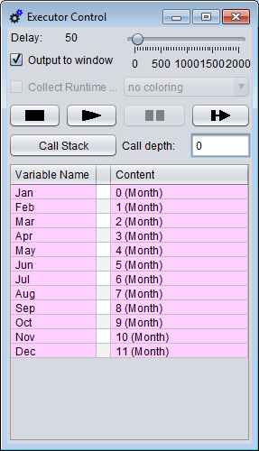
|
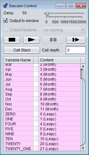
|
Displayed enumerator elements after
the type definition "Month" |
Enumerator elements with explicitly
associated code (type definition "Leapy"
below the "Month" enumerator elements)
|
You may inspect or change structured values by pressing the associated pulldown button in the central column. This will open a table view similar to the variable display, allowing to inspect (and possiby modify) the content in a structured way:
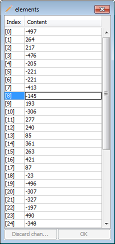
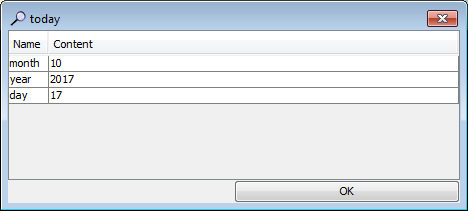
The value inspection works recursively into nested data structures. The respective title string reflects the access path:
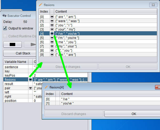
If the inspected value was a constant then you will not be able to apply changes, the icon will be a magnifying glass instead of a pencil, and there is only an "OK" button instead of a "Discard" and a "Commit"/"OK" button.
Variables of an enumerator type may show the symbolic name of their value in the variable display rather than the integer code. For variables not explicitly declared this may sometimes fail (then you will just see the internal code, see left figure below). If an enumerator value is part of a structured data chunk then it will always be represented by its integer code. If you open the table view for such a complex value as described above such that the enumerator value would have its own row then it will show the symbolic name. If the symbolic enumerator name is shown then you will sensibly obtain a choice list on double-clicking the cell in order to edit the value (see right figure below):
|
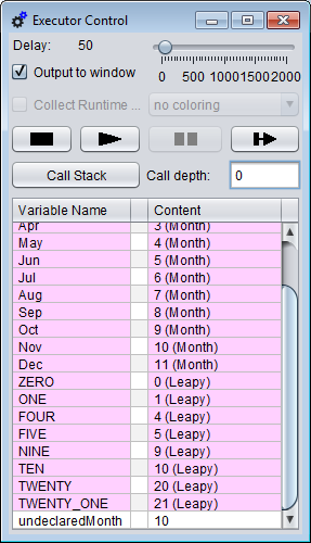
|
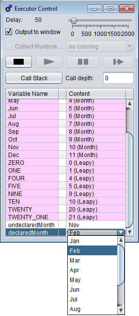
|
Display of enumerator value with
missing type information |
Choice list on editing an enumerator
variable after successful type inference |
When you resume the execution, the algorithm will continue with the modified value(s). Note that the Start and Step buttons will be locked until you finish or discard editing (by <Enter> or <Esc> or by clicking elsewhere).
Animation
The currently executed or paused instruction is highlighted with an amber background. Compound elements with pending execution, i.e. nested components of which being currently executed (or paused), are highlighted in a cream tinge. So you may easily follow the execution progress (see image in next section).
Within PARALLEL elements, those parts of the threads that have already been passed are also marked with the cream tinge; because of the randomly leaping execution you would otherwise hardly be able to tell how far the different threads may have proceeded.
Additionally, in Runtime Analysis mode, elements already passed by one of a series of performed test executions can be highlighted in bright green to visualize test coverage. Alternatively, elements may be highlighted in a spectral colour range depending on their relative execution count or the number of involved "atomic" operations. This colouring is lower prioritized than the above mentioned highlighting for the current execution status (currently executed element and structured elements with pending execution completion).
The speed of the animation is controlled by the delay slider in a range between 0 and 2000. The default is 50.
CALL execution
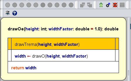
If you pause at a CALL element (maybe you reached it in step mode, or a breakpoint was set on it or you happened to press the Pause button when Executor was going to run into it, see screenshot above) then the Pause button will be substituted by a button with the following symbol:  (in versions ≥ 3.30-14).
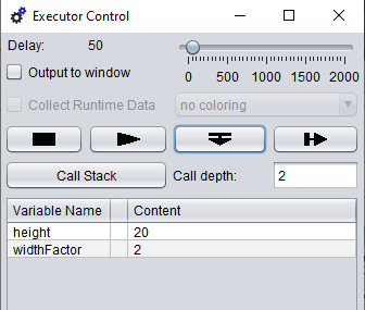
Now you will have the choice among two different ways to handle the CALL on further debugging in stepwise mode:
 (Step into): This will immerge into the called subroutine diagram and execute it element by element in step mode.
 (Step over): This will execute the subroutine as a whole and pause at the next element after returning from the CALL.
Before version 3.30-14, the Step button always descended into the CALL. In order to step over it you had to use the Run button after having placed a breakpoint behind the CALL (which was inconvenient and not even always possible, e.g. at the end of a routine or sequence).
Breakpoints
You may place breakpoints on as many elements of your diagram as you like. Execution will pause as soon as an element with breakpoint is reached (for possible actions in paused state see above).
To set or remove a breakpoint select the respective element and now either right-click and select/unselect menu item " Toggle breakpoint" in either the "Debug" or context menu or double-click and select/unselect the checkbox "Breakpoint" at the bottom of the element editor. Alternatively, you may press accelerator key <Ctrl><Shift><B>.
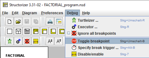
In the diagram, a breakpoint is shown as a horizontal red bar at the top of the element frame (except for REPEAT loops, where the red bar will appear between loop body and exit condition, sensibly):
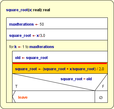
If you place a breakpoint on a loop (FOR, WHILE, REPEAT) then the execution will pause every time the loop condition is going to be checked again.
Note that you can't place a breakpoint on an ENDLESS loop (since it does not have any means of control). You may place a breakpoint on the first element of its body instead.
While Runtime Analysis mode is active you can also make use of conditioned breakpoints: You may specify an execution count value that is to trigger the breakpoint on going to be reached. That means while the element hasn't been executed as often as specified, the breakpoint will be passed as if it weren't there. Only when the current execution count (on entering the element) exactly equals the specified trigger value minus one (such that it would draw level with it on completion), the breakpoint will go off. Conditioned breakpoints are shown as a dotted red line, and their trigger value will — coloured in red — precede the runtime counts as shown in the T(RUE)-branch in the following screenshot (where the result assignment just triggered it):
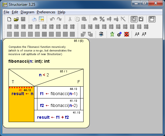
A trigger value of 0 specifies an unconditioned breakpoint as described before.
Since a conditioned breakpoint won't fire again after the (non-zero) trigger count has been exceeded, you are allowed to modify the trigger value whenever the execution is paused. To do so for a selected element you may use the menu item "Specify break trigger..." in menu "Debug" or in the context menu, or just enter the key combination <Ctrl><Alt><B>:
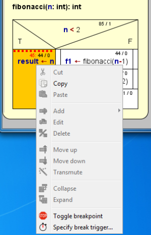
Wenn you toggle off the breakpoint then its trigger value will not get lost but is preserved for later re-activation.
In order (temporarily) to disable all breakpoints over all diagrams at once press the speed button  in the toolbar or the respective menu item "Ignore all breakpoints" in the "Debug" menu (see menu screenshot farther above). Note that this is the new effect of the button / menu since version 3.31-02; in prior versions it eliminated all breakpoints from the current diagram, but the usability of that behaviour had turned out to be very poor: during recursive execution it did not affect other instances of the routine on the call stack (such that cached breakpoints reappeared like zombies, see third note below) and to reactivate the lost breakpoints they had to be placed individually again.
Note:
- Breakpoints are not saved to file.
- To set, modify, or remove a breakpoint will not induce an entry in the undo or redo stack. However, any undoable (substantial) change to a diagram will be associated with a snapshot of all currently set breakpoints, such that on undoing a previous diagram modification the former breakpoint status would be restored. The same holds on redoing formerly undone modifications.
- If you place a breakpoint on an element within a recursive routine during execution then the breakpoint will only apply to the current and all new deeper call stack levels, but not to outer levels. And it will be gone after execution if you had placed it in a recursion depth > 0.
Output Console Window
By selecting the "Output to window" checkbox you will open a text window logging all done output and input, as mentioned in section Executor Control above.
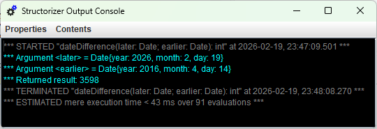
On starting execution, any previous content gets deleted, an automatically generated meta-line will name the executed program (or top-level routine) and show the starting day and time (in light-gray letters). Conversely, on terminating an execution a similar meta-line with the termination time will be displayed (see image above). Since version 3.32-35, the date will be expressed in ISO style (YYYY-MM-DD), and the time will not only show hours and minutes but also seconds and milliseconds. In addition, an estimated upper bound for the elapsed mere compute time in milliseconds (or microseconds if it is below 1 millisecond) and the number of executed basic operations ("evaluations") will be given. (This time span is no reliable benchmark at all, it is only meant as a rough orientation. On repeated execution the displayed time may vary whereas the basic operation count will not. For further explanation see Issue #1228.)
There is no way to input or edit something in the logging window. Input instructions will always be carried out via an interactive question box, but both the automatically generated prompt text and the input will be reflected here (the former in yellow colour, the latter as green text for better distinction). The regular output produced by the algorithm output instructions is shown in white colour. Every output instruction induces a new line:
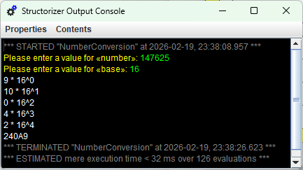
With checkbox "Output to window" not being selected, the window will just stay hidden but still exists in the background and gathers the texts printed during execution. There is an important difference with respect to the way output works, however:
- In switched-of mode, each output instruction will pop up a message box and pause execution until you confirm. The output will additionally be logged in background to the hidden window.
- With "Output to window" selected, all output is only written to the (displayed) output window without pausing. So this mode relieves you from the necessity to confirm every single output and allows continuous execution flow (which is particularly helpful with algorithms generating a lot of output).
You may change the output option at any time during or after an execution without losing the window content. If you happened to close the window via its close button then don't panic: Every output or input action of the algorithm will bring it up again. Moreover, you may reactivate it by unselecting and re-selecting the "Output to window" checkbox or, of course, by starting a new execution.
The font of the output window may be changed by menu, via the + and - keys on the number pad in combination with the <Ctrl> key, or (since version 3.28-01) via the mouse wheel with the <Ctrl> key being pressed:
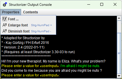
Execution errors will also be logged in red colour to the output text window after having popped up as error message box. See an example in section "Syntax > Custom subroutines".
Via the "Contents" menu (since version 3.28-07) you may switch off the logging of the Executor meta texts (like the start and termination time, reports on variable value manipulations in the value display during pause and so on). By default, the logging of these messages is enabled:

On the other hand, you may switch on an indented tracing of subdiagram calls — both on entry (marked with prefix ">>>") and exit (marked with prefix "<<<"), which is a particularly nice feature to demonstrate recursion. If the call level exceeds the value of 40 then the level is numerically given in brackets rather than further indented:
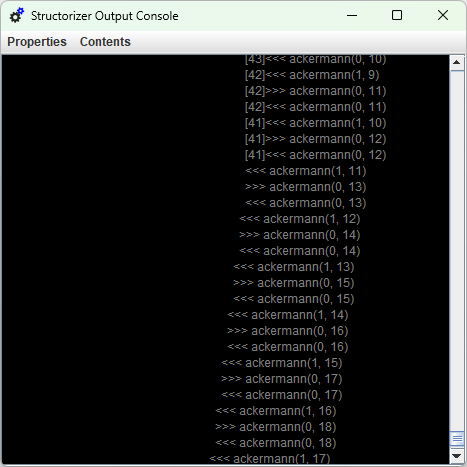
Saving the window contents:
Of course you may always select a subsection of the window content (or the entire log via <Ctrl><A>) and then copy and paste it e.g. to some text editor. This may fail with very huge logs, however; so instead the menu item "Save log ..." in the "Contents" menu (see above) is recommended, which allows you to save the current window content to a text file of your choice.
Used text colours
| Colour |
Kinds of messages |
| white |
Algorithm output |
| yellow |
Input prompts |
| green |
User input |
| gray |
Start and termination info, call entry and exit |
| cyan |
Subroutine argument input and result output (if executed on top level) |
| red |
Error and abort messages, value manipulations in the variable display |
Call Stack
As mentioned in section Executor Control above, you may display the call stack (makes only sense with diagrams containing — possibly nested — CALLs, of course). By clicking the button "Call Stack" you open the stack trace window. To display a call stack requires a begun execution (of a diagram containing CALL elements) being currently paused (e.g. by pause button or breakpoint or in step mode).
The top line always represents the innermost call (i.e., the currently executed subroutine call), the bottom line (level 0) stands for the main program or routine initially started. Some examples for call stack views are shown below:
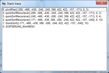
Scrollbars are automatically added when required, e.g.:
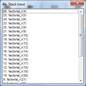

Restrictions And Trouble During Testing
If you try to start Executor for a diagram while you haven't terminated another debugging session (say you have looked for certain other diagram from Arranger in paused mode and forgotten that the debugging is still pending or you just pressed the  button again while the Control panel is hidden somewhere behind the current window), then you will be warned by a message box saying that there is a running execution:
Now you have two options:
- To abort the pending execution in order to start a new one.
- To back off by pressing "No", which will bring the possibly hidden or iconized Control panel up to top (such that you will not even have to look for it among the open windows) to facilitate resuming execution.
Likewise, you may get such a choice if you try to edit a diagram while its execution is pending (which would cause inconsistency of the Executor state). Some modifying actions are just disabled during execution, however, so selecting them won't have any effect.
In very rare cases, however, e.g. after some unexpected internal malfunction or if you managed to circumvent the edit protection in paused state, the Executor may get stuck in an inconsistant state. So you may see the above message box but aborting the current execution just doesn't work, i.e. on your next attempt to start the debugging again the same message occurs and so forth on end. Or you decide not to abort the execution but to resume and this fails. Then the only reliable way to get rid of the resilient zombie session will be to close down Structorizer (after having saved all relevant changes, of course) and to reopen it.
7.6. File I/O API
File I/O Fundamentals
A file is a resource administered by the operating system (OS), situated in the file system and identified there by a file path. A program that is to work with some file will have to observe the following mandatory phases:
- Opening of the file for the intended access type (read / write);
- Access to the content according to the requested access type;
- Closing of the file as soon as access is completed.
More precisely, it is by no means certain that the opening attempt will succeed such that a failing must always be taken into account. So it's worth to remember the following abstract algorithmic schema for dealing with files inside a program:
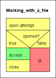
The yellow elements are the auxiliary instructions and tests dealing with the resource acquisition and release, the green element symbolizes the actual file processing, the red element represents the error path. A somewhat safer way is to make use of TRY blocks (as introduced with version 3.29-07) to ensure an opened file will get closed, no matter what happens during access (you will find some less abstract examples below):
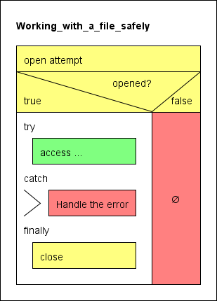
Please look on the Syntax page for the table of the file routines made available with release 3.26.
Opening a file
Consequently, a program or routine must first request a file from the OS for a certain purpose (reading or writing) before it can work with it. Structorizer offers three different opening functions — one for reading access (fileOpen) and two ones for writing access (fileCreate and fileAppend):
fileOpen requests a file identified by a path string (e.g. "documents/nice_to_have.txt") for reading data from it (i.e. as input file) and requires the file to exist and to be readable with the permissions of the user.fileCreate requests a file with the given path for writing data into it (i.e. as output file). In contrast to fileOpen the file is not required to exist before but the directory must grant the user writing permissions. If a file with this path had existed then it will be emptied without previous warning.fileAppend requests a file (may exist or not) for appending text to its end (i.e. as output file), which requires writing permissions, of course.
Any of the three opening routines returns an integer value, which in case of success serves as program-internal identifier and file handle for all the access operations you may perform with the opened file. Numbers greater than zero are valid file handles whereas numbers less than or equal to zero signal that the open attempt failed:
- 0, -1: unspecific IO error
- -2: file not found (in case of
fileOpen)
- -3: insufficient permissions
You should always test whether you obtained a valid handle by the applied opening function! If you obtained a positive number (i.e. a valid file handle) then you may apply the appropriate file-related functions or procedures, always providing the file handle as first argument. Any of these subroutines are illegal if the file handle is 0 or negative or if it was not obtained by an opening function, if the kind of access doesn't match or if the associated file has already been closed inbetween.
Closing a file
As soon a s you don't need to write or read to/from a file any longer you should make sure to close the file using procedure fileClose (with the file handle as argument). This releases the file as resource and — in case of a file opened for writing — flushes the associated buffer, ensures the file consistency in the file system, and thus makes the file available for other processes and applications. Only after having closed the file you may be sure that the data are persistently stored in the file system.
Once you have closed a file, the handle value gets stale, i.e. it cannot be re-used for file operations. Even if you reopen a file that you have used before you will obtain a new, different handle. The procedure fileClose must not be applied a second time to a file aleady closed.
Reading from a file
You can only read from a file if it had been opened by means of fileOpen before and you must use the file handle obtained from fileOpen as routine argument. These are the available reading functions:
fileReadChar will return the next character of the file (including a blank or newline character).fileReadInt will return an integer value if and only if the next token in the file is an integer literal, otherwise it will raise an error.fileReadDouble will return a floating-point number if and only if the next token in the file is a number literal (be it integral or not), otherwise it will raise an error.fileRead may return:
- an integral number if an integer literal (e.g.
-17) follows at the current reading position;
- a floating point number if a floating-point literal (e.g.
3.6e17) follows at the current reading position;
- an array of simple-type elements if a comma-separated sequence of primitive-type literals, enclosed in curly braces, (e.g.
{0, 25, foo, "text without commas", 6.9}) follows at the current reading position;
- a string consisting of the content of a quoted character sequence (e.g.
"This text, however, might contain commas, but no escaped quote") following at the current reading position;
- a string comprising the next character sequence not interrupted by a blank (e.g.
foo) in any other case.
fileReadLine will always return a string comprising the (remainder of the) current line up to but not including the next newline character. The newline character will be consumed, though.
Since reading beyond the end of the file raises an error, it will generally be a good idea to check the "end of file" property of the file being read. This is done by function fileEOF, which returns true if the file end is reached and false otherwise. Use see its use in the examples at the end of this section.
Writing to a file
You may only write to a file if you obtained a valid (i.e. positive) file handle from one these two opening functions: fileCreate or fileAppend.
fileWrite will write an arbitrary value just as is — without any additional separators, line feeds etc. This allows to compose arbitrary texts without Structorizer interference.fileWriteLine will do the same but add a newline character.
Examples
The following examples may illustrate how to work correctly with files:
1. FileWriteDemo
FileWriteDemo just writes text / values obtained via an input instruction to a file, separating all values by a space character (which is the "natural" separator for reading tokens from a file) until the user enters a single '$' sign. This will result in one long line of text in the file. The failure path is empty, but you might insert an output instruction with an error message (see example 6 below).
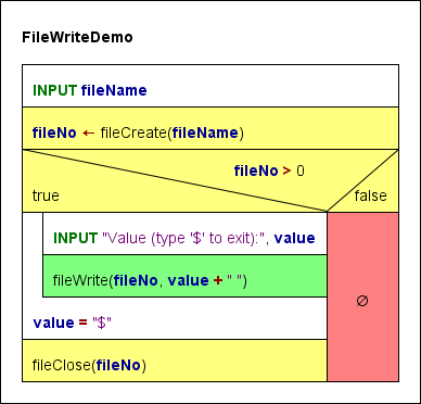
2. FileReadDemo, FileReadDemoTry
FileReadDemo goes the opposite way: It opens a text file and reads tokens (substrings separated by white space) from it — one per loop cycle — tries to interpret them as numbers or by default strings and writes the interpreted values to the output one by one. Be aware that the values read may not be equivalent in number and type to the expressions you wrote into that very file. E.g. a written non-quoted string with spaces will be split to the "words" on reading the file, and each of thes "words" (tokens) will independently be checked for literal syntax, such that a written string These are 4 words will be read as four values, three of which (the 1st, 2nd, and 4th) being strings, one (the 3rd) being an integer value.
If the file contains quoted strings i.e. several words, the first of which starting with " and the last of which (within the same line!) ending with ", then this sequence will be read as one string, the quotes being dropped.
If the file contains comma-separated tokens between curly braces, e.g.
{23, 7, -9.8e4, "something"}
then at least the attempt to convert this into an array will be made.
With this respect, you may find the new built-in test functions isArray, isNumber, isString, isChar, and isBool helpful in order to be capable of making use of the values read from file.
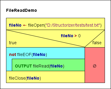
Since version 3.29-08, you may go an even safer way by encapsulating the file access in a TRY block in order to make sure the file will be closed:
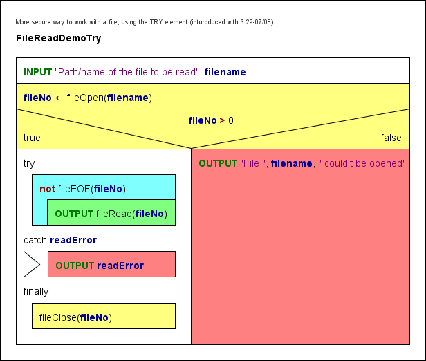
3. FileReadDoubleDemo, FileReadDoubleDemoTry
This algorithm relies on the assumption that the text file consists of several white-space-separated character sequences inerpretable as floating point numbers, e.g.
4.5 -98.0e5 7
12 10293
It reads the values from the file as double values into an array and then writes the array elements to the output. A token not interpretable as number will abort the algorithm.
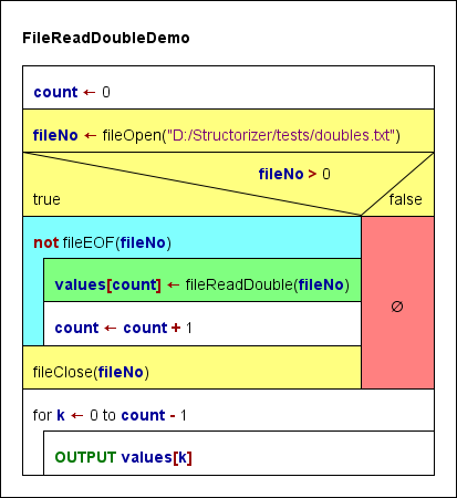
Again, this algorithm could be made a little safer by using a TRY block. The output of the array was put into the protected section as well (though this postpones the closing of the file) because array values was only introduced within the reading loop, so it might not have been initialized in case of an error, which might cause the execution to crash if the array were accessed after the TRY block:
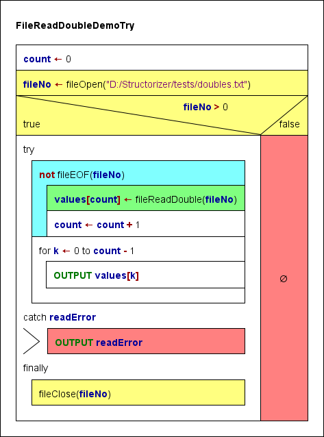
4. FileReadCharDemo
This algorithm reads the input file given by the requested path character by character (including all whitespace characters otherwise ignored!) and writes both the graphical representation and the decimal code of each character to the output stream.
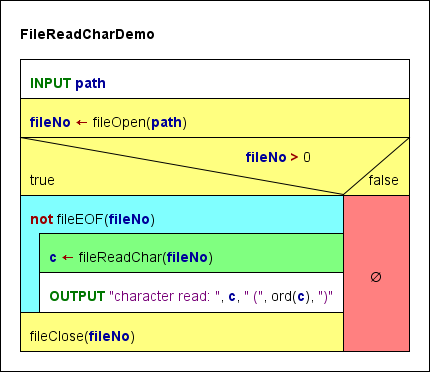
5. FileAppendDemo
This algorithm tries to open a text file for writing without clearing its previous content and appends the interactive user input as additional lines to its end. The user may exit the loop by leaving the text input field empty.
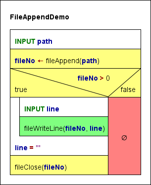
6. FileCopy
The last diagram example demonstrates how to copy a text file line per line. The cyan elements are related to the source file, the green elements refer to the target file. The red and pink elements are the error paths for the opening attempts.
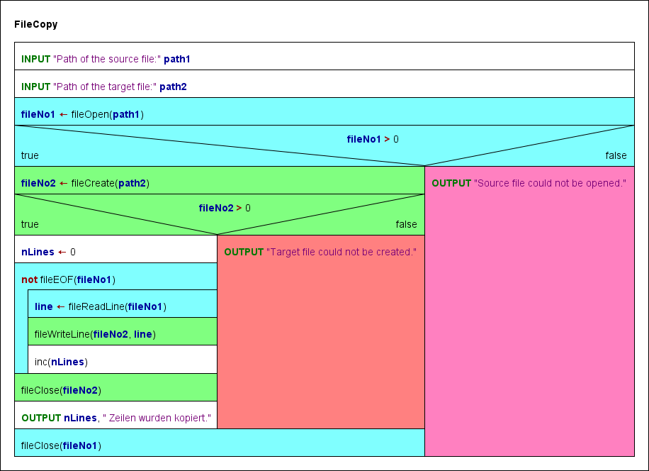
Code export
Efforts were made to enable the code generators of Structorizer to produce a more or less sensible equivalent of algorithms using the Structorizer File API routines in the target code. With some languages a relatively simple transformation could be found, for others (e.g. C++, C#, Python) a static object class "StructorizerFileAPI" emulating the Structorizer File API may have to be inserted into or attributed to the resulting code where an in-place substitution was not feasible. The Java export just adds some private static methods to the resulting class itself.
Very different types of file handles or an exception-based function concept made it utterly difficult or even impossible to concoct some halfway compatible test for success or would require to redesign the entire context of the algorithms.
The code export to the shell script languages bash and ksh had to capitulate to the completely different paradigm of handling files, where you would have to redirect standard input or output to text files. File output can be done by sporadic echo appending to the target file (echo $value >> $filepath) but input can only be done in one single loop because there is no explicit file descriptor keeping a reading position between sporadic access attempts.
Therefore, a full (100 %) semantic equivalence may not be expected, not even with high-level languages, though their file concepts are roughly comparable.
Structorizer still doesn't offer export solutions for Oberon and BASIC. Approaches may be added with later versions, though.
7.7. Runtime Analysis
Motivation
Once an algorithm is designed, several questions arise: Will it work? Will it always produce correct results? Are there redundant parts? Have my tests covered all possible cases? What about the performance, is it acceptable, is its functional dependency on the "problem size" within the predicted bounds? If we consider to optimize the code, where should we begin?
Runtime analysis tools collecting data during the execution of an algorithm can help answer many of these questions.
That's why Structorizer now offers several specific visualisation options for the analysis of the algorithm behaviour and the test strategy.
Testing is an important approach to validate an algorithm. An essential criterion for a systematic and exhaustive white-box test is so-called code coverage, i.e. ensuring that every single path of an algorithm has been passed at least once.
Besides the meticulous planning of a minimum set of necessary data tuples (input + expected output) to achieve this, a convenient way to prove and demonstrate that all paths have actually been executed (covered) by the driven tests is necessary.
The latter is where Structorizer comes in: Runtime Analysis is a feature within the Structorizer Executor being able to demonstrate the completeness of a set of tests.
Entering the Runtime Analysis Mode
To activate the Runtime Analysis, invoke the Executor:

There are a checkbox and a choice list for the kind of visualised data in the third line on the Executor Control panel:
[v] Collect Runtime Data: switches the tracking of execution counts on (or off).
The alteration of the checkbox state is only enabled between tests, never during an execution, no matter whether being running or paused. For the availability of the choice list on the right-hand side, only the checkbox "Collect Runtime Data" must have been checked. (That means you can switch the type of presented data during the test, the selected visualisation has no impact on the collecting process. See "Freedom of Choice" further below.)
Note: When you unselect the check box, however, then any collected data are immediately erased and all run-data-related highlighting is switched off. Hence, if you just want to suppress highlighting without stopping the tracking and keeping of runtime data then select visualisation mode "no coloring" instead.
If the Runtime Analysis is enabled it cumulatively collects and counts several data about the execution of the Elements. You have then the opportunity to visualize different aspects of the collected data. These are:
- Test coverage (has the Element been executed at least once?)
- Execution count (how often has the Element been passed during the test?)
- Number of performed operations by the element itself (how many atomic operations has the Element performed?)
- Aggregated number of performed operations (if the element is composed then how many operations were commanded as part of this structure)
Since the range of the latter two annotation types may be huge (from 0 to many millions and more), both a linear and a logarithmic scaling is selectable.
According to the visualization type selected, the colouring of he elements changes live during the execution. So you may follow what happens. The delay glider allows you to slow down the process sufficiently to follow the changes or to reduce delay in order to get faster to the results.
While Runtime Analysis is active, two numbers (counters) will appear and increase in the upper right corner of each element, separated by a slash. The first number represents the execution counter, the second one is the number of local (or aggregated) atomic operations commanded by the element. Their meaning and difference is explained in more detail further below.
Test Coverage
If you choose shallow test coverage or deep test coverage in the choice list on he right-hand side, then all elements performed at least once during the recent series of executed tests will be highlighted. The highlighting colour of these "test-covered" elements is a brilliant green:
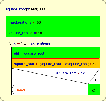
Partially covered function diagram, currently pausing at the breakpoint (execution markup is prioritized over coverage markup).
Coverage Rules
The rules are quite straightforward:
- Simple instructions and Jumps are marked after their first complete execution. Empty elements (e.g. empty FALSE branches of IF statements) also must have been passed before they turn green.
- Structured forking elements (IF statements, CASE selections, and PARALLEL sections) get only marked when all their branches have been covered completely, i.e. turned green.
A specific aspect concerns CASE selections without default branch: Since a missing default branch does not mean that a discriminator value not matching any of the given selector constants were an error – but just lets it pass by –, this structure is actually equivalent to a CASE selection with empty default branch. It is often used if there is no real chance that the discriminator expression might yield a value not among the selectors, but it is not required to be so. Therefore, version 3.25-09 introduced the following distinction: in shallow coverage mode a simplified CASE will be marked as covered as soon as all explicit (i.e. visible) branches are covered, a deep coverage, however, can only be achieved after the hidden default branch had also been passed at least once, such that the following situation may occur (shown in deep coverage highlighting, shallow coverage highlighting would present the entire diagram in green):
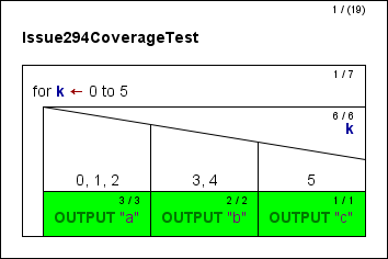
- Loop elements turn green on leaving if their respective loop body has been completely covered, i.e. a head-controlled loop will not turn green if the loop body was bypassed.
- For subroutine CALLs there is a deep and a shallow mode. In deep mode, the called subroutine itself is part of the test and must first completely be covered before the CALL element invoking it may turn green as well. The shallow mode, in contrast, assumes that called subroutines will have been tested before and proven to be correct. This does not mean the subroutine wouldn't be tracked, instead it just doesn't require the invoked routine to be covered completely in order to turn the CALL green.
- While the shallow mode treats all subroutines as if they were covered, you may also selectively mark some subroutines parked in the Arranger as formally covered – and adhere to deep mode for the remaining subroutines. (This way, some subroutines are subject to thorough coverage testing while others are not.)
Use the button  "Set Covered" in the Arranger toolbar (or the context menu item
  "Test-covered on/off" in the Arranger index) to mark a selected diagram as covered. (The button is only enabled in Test Coverage Tracking mode.) A subroutine diagram marked this way will be recognizable by its green outer frame while internal elements are not necessarily highlighted, see image below. (But don't forget that this green colour will only show while one of the visualisation modes "shallow test coverage" or "deep test coverage" is selected!) In the Arranger index, however, the diagrams marked as test-covered will show a green-bordered icon
  while Runtime Analysis is active (no matter, which visualization mode).
- The case of recursive CALLs is even a little bit more tricky: If tracked in deep mode, a recursive routine could never become covered since turning it green would require the contained recursive CALL have turned green, which in turn requires the routine be green etc. ad libitum. Hence, a CALL detected to be recursive is ALWAYS tracked in shallow mode to get out of the vicious circle. Note that his does not mean, that the recursive routine itself would automatically be marked, it only gives it the chance!
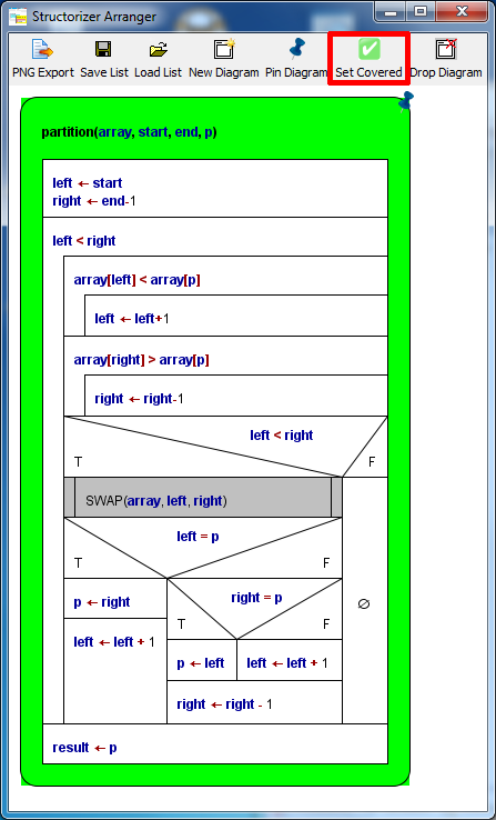
A subroutine diagram in the Arranger window marked via the "Set Covered" button (in red box).
Be aware that the coverage mark around the diagram is only visible while one of the coverage visualisation modes is active. In the Arranger index, however, the respective icon  indicates this state with all visualisation modes, provided the Runtime Analysis is enabled.
Remarks
Coverage marks are not stored when saving a diagram to a file. Neither are the count values.
Editing a diagram will clear all collected runtime data and marks, but the numbers are cached in the Undo list. So when you undo the changes then the previous coverage state will be restored and allows you to continue with that constellation.
Complex example
The following three images show phases of a code coverage analysis with Structorizer. The main program is a test frame (diagram at lower right corner in the Arranger window) for a recursive QuickSort algorithm with several nested subroutines (diagrams arranged in the remaining Arranger window area). The first image shows a running test (be aware that there are several "open" subroutine calls at different levels at the same time, recognizable by the orange element colour), the remaining two images show the situation after some more executed tests.
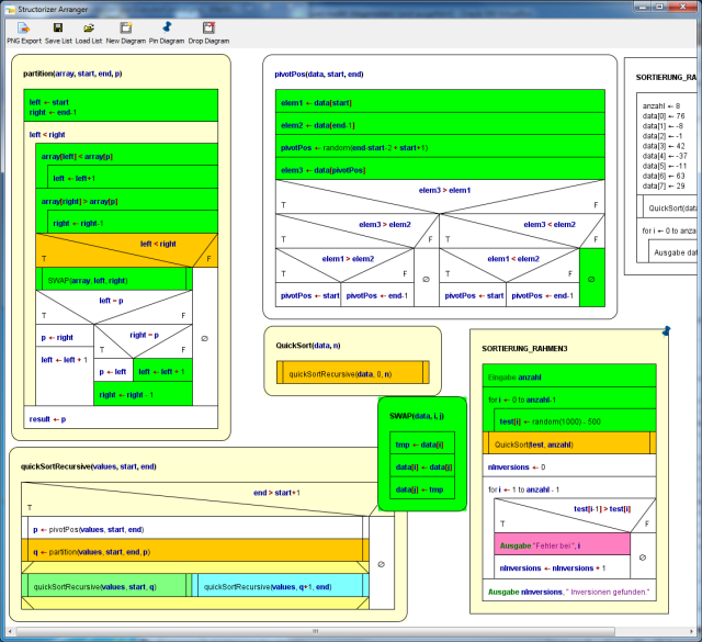
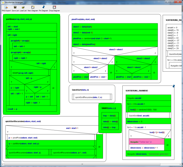
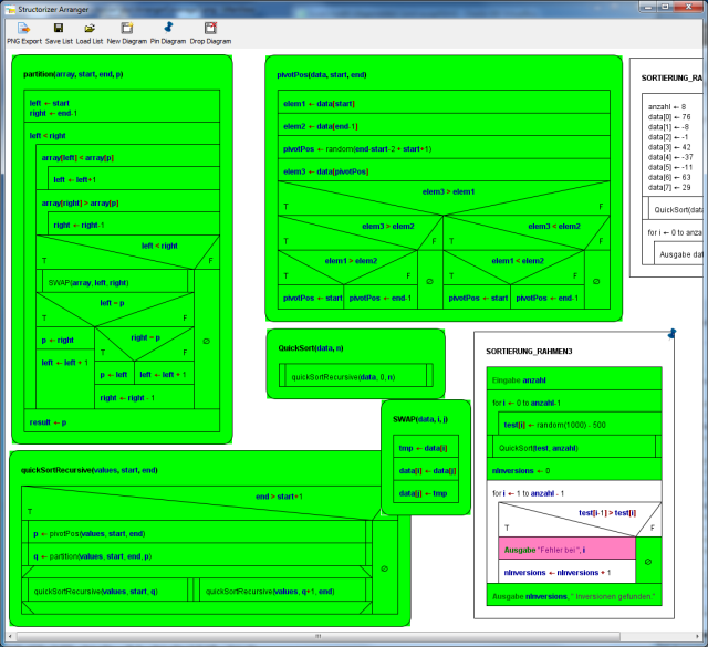
After this last phase in deep mode, all subroutines are completely covered. This does not hold for the test program "SORTIERUNG_RAHMEN3" because the sorting algorithm always worked correctly such that the alert branch (with the pink output instruction) has never been passed. In order to provoke an inversion (i.e. a sorting mistake) detection, routine "QuickSort" might be replaced by a dummy (with same name but not actually sorting) before the next test. This would accomplish the coverage.
Execution Counts (or Transit Counts)
The first one of the two small counts in the upper right corner of the elements represents the number of times the element has been passed during the tests. (All elements with execution counts larger than zero are "test covered", at least in the shallow meaning, see above.) The execution count does not increment before control flow has left the element. This means in case of a structured element (like Alternative, CASE, or loops) that some control path through its substructure must have been completed. Analogously, in mode "Hide mere declarations?" this holds for an instruction being the drawing surrogate for a "collapsed" (hidden) sequence of mere declaratory elements: The excution count will not be incremented before the last of the hidden elements has been passed.
If you select execution counts in the display choice list then the elements will be coloured according to that first count number in a spectral range from deep blue to hot red, where deep blue stands for 0 and hot red for the highest count value over all the involved diagrams.
The following image shows a NEWTON algorithm (used for the computation of square roots), here after the calculation of the square root of 25:
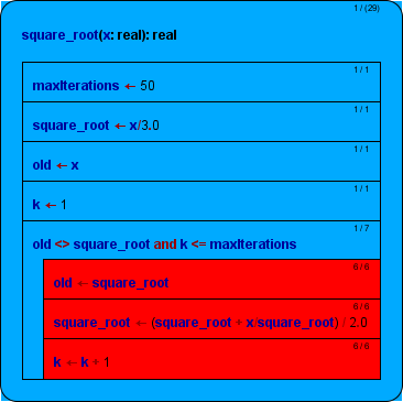
As you can see, the WHILE loop was entered and left only once but the loop body had to be repeated 6 times. So 1 is the smallest and 6 is the highest existing count, and there is nothing inbetween. Hence, only two colours occur. (And since within the range of 0...5 a step of 1 is relatively rough, the blue isn't that dark as one might have expected with value 1.)
This analysis shows e.g. where a code optimisation would be essential if possible (red areas) and where it would not be worth to be considered (blue areas).
Operation Load
The second one of the two small numbers in the upper right corner of an element represents the load of the "atomic" operations (right-hand side of the slash).
If you select done operations lin. or done operations log. then the tingeing of the diagram elements is done by either linear or logarithmic scaling of the number of "atomic" operations, respectively. The logarithmic scale is more sensible if the range of the numbers is very widely spread.
The difference between execution count (number of element transits, see above) and the load of "atomic" operations an element is directly responsible for becomes clearer with the following image, wich only differs from the above situation by the focus of visualisation (where the linear scaling was chosen):
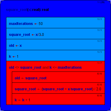
As you may see, here the WHILE loop turned red, too. This is because now every single condition examination counts as an operation (thus costing time). In order to perform the loop body 6 times, the condition has to be examined 7 times (once on first entering the WHILE element, then after each loop execution i.e. before the next iteration, amounting to 7).
Hint: Sometimes users are puzzled by Alternatives showing a high count on the condition but very low operation counts on both branches. This situation will typically occur if one of the branches is empty – an empty element doesn't carry out anything, so it's operation load will always stick to zero! (But look at the transit count in such a case!)
Attribution Rules
The operation loads for the different kinds of elements are:
- Instruction element: Number of instruction lines within the element. Note that
- an empty element will constantly show 0, no matter how frequently ever it may have been passed!
- mere type definitions won't contribute to the operation loads, either, though they are passed at runtime by Structorizer – they are regarded as mere declaratory information usually evaluated by a compiler before excecutions starts. Well, it might of course be disputed why then constant definitions and variable declarations (even without initialization) are counted as operations, because in many compiled languages they are also translated at compile time and won't do anything at run time. But in Structorizer they actually modify the environment state at execution time (computing and assigning a value to the constant or allocating virtual memory to the variable, respectively).
- EXIT element: 1;
- CALL element (on its own): 1 (it costs time to organise the stack descending);
- IF element: 1 for the evaluation of the condition;
- CASE selection: 1 for the evaluation of the distributing expression;
- FOR loop: 1 + n (Initialisation and first test as one operation, increment and test on every repetition);
- WHILE loop: 1 + n (First test and then one further test with every repetition);
- REPEAT loop: n (test after every body execution);
- ENDLESS loop: 0 (no test);
- PARALLEL section: 0 (the synchronisation effort was neglected here);
- TRY block: 0 (the stack unwinding effort is attributed to the throw Jump; if an exception type classification will have to be done in a future version then it might change to 1 in case of catching an exception).
If an element is passed several times then of course the values above will multiply by the number of transits, as you may see with the simple instructions forming the loop body in the diagram above. (The load of the FOR loop should actually be 1 + 2n as it is test plus increment per cycle, which would count separately in an equivalent WHILE loop, but we simplify a little here.)
Note that these loads do not include the loads of the substructure elements. It's only the own contribution of the respective element itself. Only the program (or function) element, i.e. the outer frame, shows the aggregated load of operations performed throughout the entire program / routine. Therefore the parentheses around the load number. The colouring of the program / the routine, however, does not reflect the aggregated load but is based on the net operation load which is used to be zero (deep blue in the above image).
From this colouring you may learn where most of the time is consumed.
Note: With recursive algorithms, the operation loads give only a notion of the time distribution on the top level (or the current level, on interruption). Otherwise the overall sum wouldn't be correct since the operation load of the analogous elements at called levels will already have been aggregated in the recursive calls being visible in the same context. This way, it is possible that the execution count of an instruction in a recursive routine is greater than its shown operation load, because the execution count represents all copies of the element whereas the operation load is bound to the currently visible level.
If you collapse a structured element, then its displayed load of operations will increase by the operation loads of the contained elements – as if they were melted together. The tinge of the element will not change, however.
So for the WHILE loop in the example above this would mean a load of 7 + 6 + 6 + 6 = 25. In this case (as the loop elements are flat instructions), it would be the number also presented by the following aggregated mode.
For sequences of declarative elements in display mode "Hide mere declarartions?" is similar like for collapsed structured elements, but that the background colour does differ from the normal display mode (where each element of the sequenec stands for itself) – the drawing surrogate for the declaration sequence will appear as its amalgamation (and be tinged like in the Total Operations Load visualisation mode).
Total Operations Load
If you select one of the visualisation modes total operations lin. or total operations log. then the tingeing of the diagram elements is done by either linear or logarithmic scaling of the aggregated load of operations, respectively, i.e. the load of structured elements also recursively includes the loads of their respective substructure. The logarithmic scale is more sensible if the range of the numbers is very widely spread.
The aggregated operation numbers on structured elements will be enclosed in parentheses to remind that these are composed data.
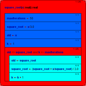
On collapsing elements, the load won't change of course (it just loses its parenthesis), nor will the colour.
This mode is fine to visualise the hierarchical aggregation and load distribution – it is all calculated already. The program element tells you the overall number of (fictitious) unit operations to accomplish the computation and may serve as an estimate for time complexity if you find the functional relation to the number or size of data to be processed.
Complex Example
Again, the colouring shall also be demonstrated with the complex example of a recursive quicksort algorithm with several nested routine levels.
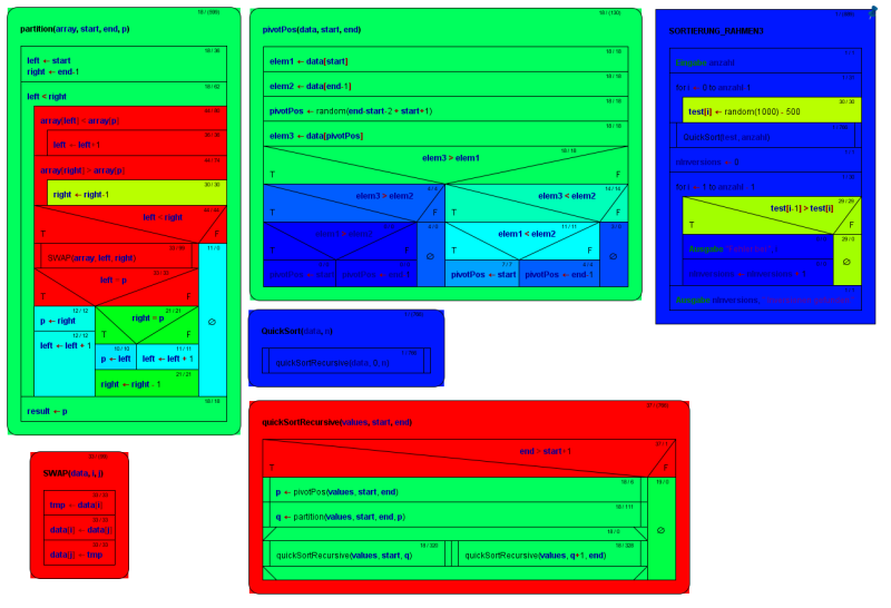
Recursive QuickSort algorithm composed of several subroutines, in Execution Count mode
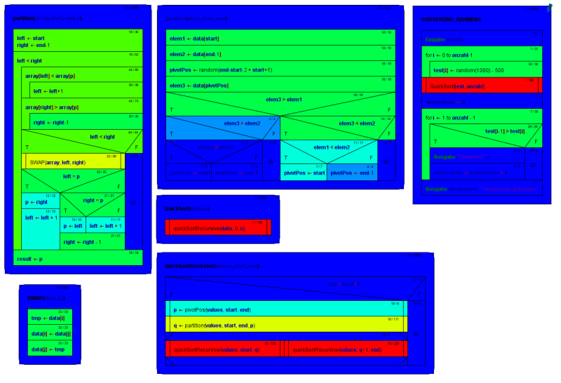
Recursive QuickSort algorithm composed of several subroutines, in local Done Operations mode
Freedom of Choice
Once the Runtime Analysis has begun you may freely switch among the different visualisation modes, export the coloured diagrams to different graphics formats, print them, arrange them, etc. until you unselect the checkbox "Collect Runtime Data", in which case all collected data are cleared and the display returns to standard mode.
As already stated for the test coverage mode, however, saving a diagram in its native file format will not store any of the gathered results. So if you want to document the results, you must export the diagram(s) as a picture.
7.8. Arranger
Purposes
The Arranger is a Structorizer component that allows you to manage a pool of opened diagrams. It is chiefly serving three purposes:
- Its original task is to offer the opportunity to graphically arrange (therefore the name) several Nassi-Shneiderman diagrams on a common canvas. Such an arrangement can be saved as PNG image, but can also be stored in a way that it may be reloaded some time later.
- In addition, Arranger serves as a pool of includable or callable subroutine diagrams for the Executor, i.e. as soon as diagram execution arrives at a Call element, a subroutine diagram with matching signature will be looked for among the diagrams parked in the Arranger. Likewise, diagrams named in the include list of an executed diagram are searched for in the Arranger.
- Closely related with the previous purpose, it may also serve to find and involve called subroutines on code export (also see export options).
Since release 3.29, the diagrams in Arranger are organised in groups, this way reflecting e.g. a common file origin, logical relations, or dependencies. Please see subsection
Groups for more details.
How to open the Arranger?
There are four different ways to open the Arranger:
- By executing the shell script Arranger.sh in a Linux environment or the batch file Arranger.bat in a Windows environment, respectively. You find both files in the Structorizer folder (i.e. where you unpacked the downloaded Structorizer package) except you downloaded the Mac OS X version. Alternatively you might start the following command from the command line, provided the Structorizer directory is the working directory:
java -cp Structorizer.app/Contents/Resources/Java/Structorizer.jar lu.fisch.structorizer.arranger.Arranger
In this case, the Arranger will start with an empty drawing area (see below how to push diagrams into the Arranger) and will play the role of the master of all Structorizer instances initiated from here. (The remaining ways below all establish the inverse Master-Slave relation, i.e. if Arranger is opened from a Structorizer instance then the latter will be the application master, whereas the Arranger and all Structorizer instances indirectly created via Arranger will depend on the original Structorizer instance.)
- By pressing the Arranger button (
 ) in the toolbox or the "
 Arrange" item in the "File" menu of Structorizer a first time. In this case, Arranger will be opened and the currently edited diagram will be pushed to the Arranger and pinned.
- By loading (or dragging) an arrangement file into Structorizer. In this case, too, the loaded diagrams will be associated to the Structorizer instance, be pinned, and form a group.
- By importing a source file, which contains more than a single main program or subroutine (and not more than the diagram number threshold configurable in the import preferences). All diagrams emerging from the source file will also form a group.
- By outsourcing parts of a diagram into a new subroutine diagram (the derived subroutine diagram will then automatically be placed and pinned in Arranger).
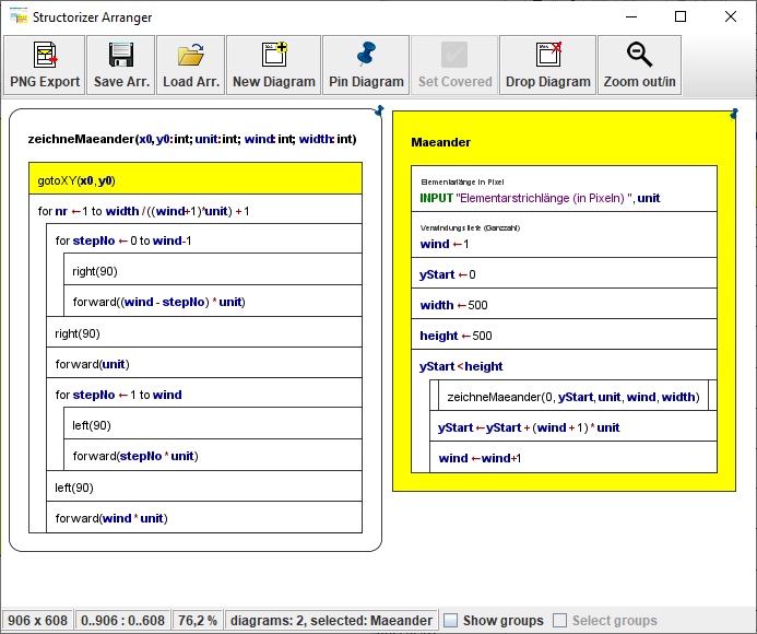
How to put diagrams into the Arranger?
There are several possible ways to put a diagram to an already open Arranger:
- Press the "New Diagram" button in the Arranger toolbar (see image above) to add an empty new diagram to the drawing area. To fill in content, just open a new Structorizer instance by double-clicking the diagram. Now you can edit the diagram in the usual way. All changes you perform will immediately be reflected within the Arranger canvas.
- Select one or more NSD files (e.g. in the respective GUI file manager of your operating system), drag the selection into the Arranger area, and drop it here.
- While working on a diagram with Structorizer, press the
 tool button or menu item "File ›
  Arrange". This way, Structorizer and Arranger will nearby be associated, and all manipulations with the diagram will be synchronized to the Arranger. The diagram will automatically be "pinned" (see image), which protects it against replacement in the Arranger when the diagram is replaced in the Structorizer.
- Press <Ctrl><C> in an open Structorizer instance while the entire diagram (i.e. the outer framing element) is selected in order to copy it to the clipboard and then press <Ctrl><V> in the Arranger window to paste it here (cf. Copy Element).
- Load a stored arrangement (see next subsection).
- Import source code containing several subprograms (see import options).
- Outsource a subsection of a diagram you work on as a new subroutine diagram, which will automatically be created in the Arranger.
- By summoning the subroutine diagram referenced by a selected CALL element into an editor if that routine diagram hasn't been in Arranger - you will be asked whether you want to create it.
Arranger does its best to find a suited free place without overlapping for any introduced diagram on the canvas.
This may not always seem to work, however, e.g. on outsourcing subroutines, because the diagrams may change their shape after having been allocated based on their former dimension. When loading a stored arrangment (5th way above), the diagrams will in mos cases be placed at the position they had when saved, so they are likely to eclipse other diagrams already residing in the Arranger. Some arrangements, however, may have dynamic allocation, particularly if they were created by
batch code import.
Since release 3.29, diagrams or groups of diagrams newly added to Arranger will automatically be selected there, such that you may instantly drag them to another place that pleases you more (see section
How to arrange diagrams below).
Before versions 3.29-06 through 3.29-09, drawing and particularly scrolling in Arranger could get inacceptably slow with a very large number of diagrams or very large diagrams. Versions 3.29-06, 3.29-08, and 3.29-09 came with some fundamental improvements in the drawing mechanism particularly in syntax highlighting mode, such that now only the first presentation of a bunch of hundreds of diagrams may take some seconds, then scrolling will be very quick.
In order to remove diagrams from Arranger, you may simply select one or more diagrams (multiple selection was introduced with release 3.29) and then press the "Drop diagram" button or the <Delete> key. If some of the selected diagrams are "dirty" (i.e. have unsaved changes) then you will first be asked whether to save or discard the pending changes. Via <Escape> you may cancel the removal attempt. For the removal of all diagrams from Arranger, version 3.28-05 had introduced a button mode "Remove All": Just press the shift key, and the "Drop diagram" button will immediately change its caption and symbol (as does the "Zoom out/in" button next to it, see next subsection) and now allows you to remove all diagrams at once:
Since release 3.29, you may alternatively use key binding <
Ctrl><
A> to select all diagrams in the Arranger. Pressing the ordinary "
Drop diagram" button will then have the same effect as "
Remove All". You may also remove diagram groups via the Arranger Index (see
below).
If several "dirty" diagrams are held in Arranger, you will be asked for each of them whether and possibly where to save them. The message box coming up in this case allows you to apply your decision to all remaining diagrams (versions ≥ 3.28-05):

Groups (versions ≥ 3.29)
Since release 3.29, you may organize diagrams in one or more groups in Arranger. The group concept was introduced to give a better overview, to improve the general handling and to allow the management of sub-arrangements as coexisting "projects", each with consistent sets of dependent diagrams (main programs with numerous subroutines or include diagrams). Hence, groups are subsets of related diagrams that can be loaded, saved, moved, and updated together and independently from others. Of course groups may add to the complexity, on the other hand.
Groups keep track of the member diagrams and their location. So any modification to these properties will set a "changed" status.
There is a default group where all diagrams pushed into Arranger are normally gathered (this is more or less equivalent to the "groupless" general diagram pool of former versions). But there are some useful exceptions: If you load an arrangement file or import diagrams from source code, then the resulting bunch of diagrams will automatically form a group named after the file the diagrams originate from. The same happens when you save an arrangement from a selected diagram subset (see Saving / Storing Arrangements) that had not been a group before: all involved diagrams will automatically form a new group named after the arrangement file you created.
Moreover, you may always select some fancy subset of diagrams and create a new group from them by pressing key combination <Ctrl><G> or by using the popup menu item "Group selected diagrams ...":
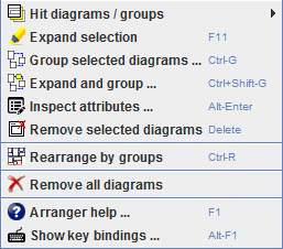
Now, how can you be sure that your selection is complete with respect to required subroutine or includable diagrams? Well, here comes the solution: You may select the "Expand selection" menu item (or press <F11>) before you create the group. This function will augment the selected set with all diagrams directly or indirectly required for contained CALL elements or include lists and tell you how many diagrams were added and what referenced diagrams are missing. You can do both at once by using the "Expand and group ..." menu item or key binding <Ctrl><Shift><G>. (You will just not be informed about the expansion and the lacking relations.)
Groups are not required to be disjoint, they may share diagrams. Or, in other words, a diagram may be member of several groups. (Of course it makes handling easier if the groups are disjoint.)
By default, groups are not visible in the Arranger drawing surface. But from version 3.29-01 on there is a checkbox "Show groups" in the status bar (see figure in section Zooming) that allows you to have Arranger showing their bounds als transparently filled rectangles. For better differentiation, the groups are automatically associated with one of upto six different colours. The bounds will appear in the respective group colours. As an additional aid, a tooltip will pop up while you move the mouse over one or more group areas, showing you the grouo names in the group colours:
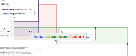
A second checkbox "Select groups" in the Arranger status bar (you may have to enlarge the Aranger window to see it) will switch the selection policy from diagrams to groups: As soon as you hit a group area, all its member diagrams will immediately get selected.
Apart from that, you may see, inspect, and manipulate the group relations in the Arranger Index tree explained further below. It is placed at the right-hand side of the Structorizer work area as to be seen in the figure:
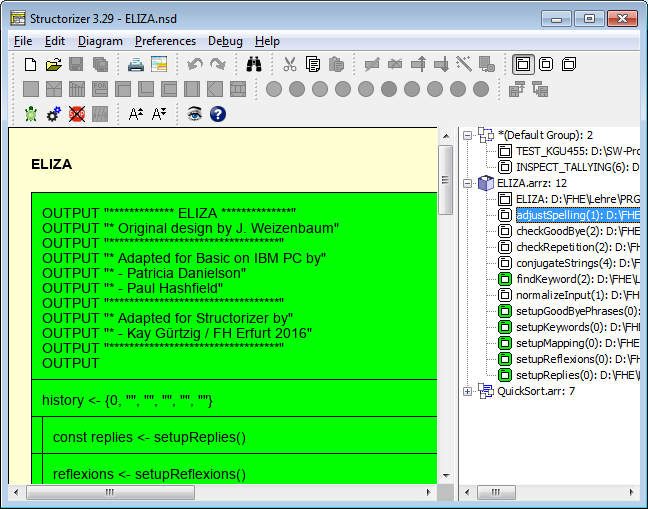
Since version 3.29-01, there is an easy opportunity to rearrange all diagrams in the Arranger by groups. This function is available via the pop-up menu item " Rearrange by groups" or key combination <Ctrl><R>. This sorts and rearranges the diagrams according to the groups where every group starts to arrange its diagrams in a new "row" (also see subsection Arranger keybindings and pop-up menu).
Zooming
Traditionally (i.e. before version 3.27-08) the diagrams had always the sime size in Arranger as in Structorizer. This tended to get impractical when there are many or large diagrams (or both) parked in the Arranger. To gain an overview of the numerous arranged diagrams, to see a preview how the exported bitmap would look like, or e.g. visually to follow the control flow through an algorithm with deeply nested subroutine calls on execution, you may now simply zoom out as far as necessary by clicking on the zoom button  or by pressing the "-" key on the number pad of your keyboard repeatedly:
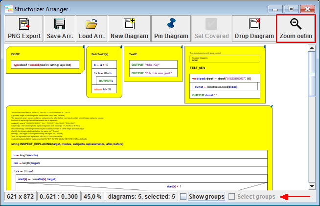
Each click reduces the size by about 10 % of its former dimensions. Since release 3.29, there is a status bar at the bottom of the Arranger window (see red arrow above) showing you the current zoom factor. The full list of displayed status information is given below (the checkboxes added with version 3.29-01 are explained in section Groups):
- the extent of the drawing area (in pixels),
- the current scrolling viewport intervals (xmin..xmax : ymin..ymax),
- the zoom factor in percent,
- the total number of diagrams / the number of currently selected diagrams (or the name of the one selected diagram),
- whether the bounds of group are shown,
- whether groups are selectable.
The layout of the statusbar has slightly changed with version 3.30-13 (icons partially replace text, new tooltip gives a brief explanation for the diagram info):

If you want to zoom in again, simply press the number-pad "+" key or hold the <Shift> key pressed and click on the zoom button, which will change its icon and effect while the <Shift> key is held down:
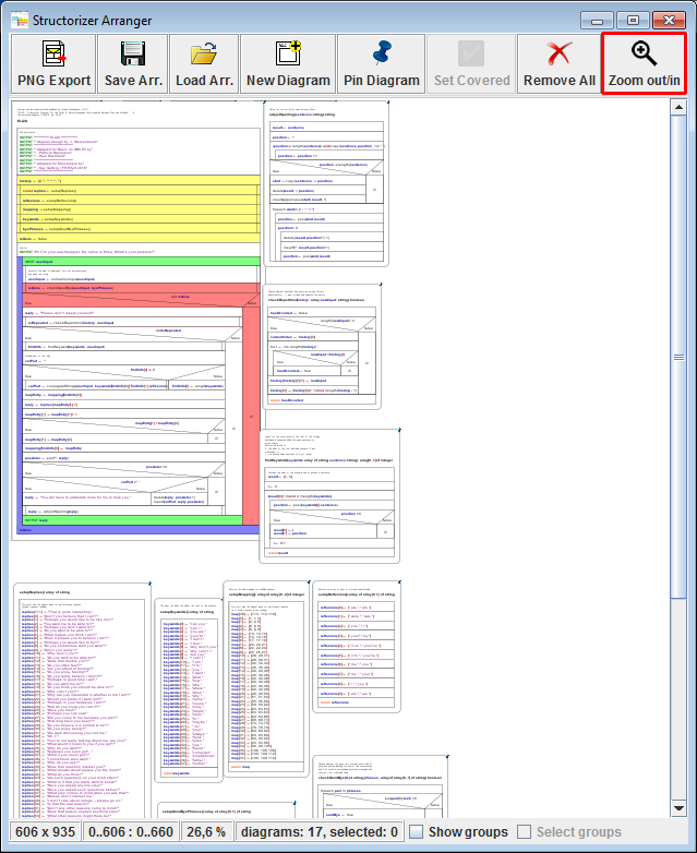
Alternatively, you may also zoom in or out by means of the mouse wheel while the <Ctrl> key is pressed, in the way known from many other applications (you may even configure the reverse zooming effect in the "Preferences > Mouse wheel" submenu).
The maximum zoom is 100 %, i.e. you cannot magnify the diagrams larger than they are currently presented in the Structorizer editing environment (as controlled by the font size).
Btw, the last zoom factor of your session is retained in your configuration file (structorizer.ini), so you will automatically start with the same Arranger zoom factor the next time you use Structorizer.
Due to rounding effects, the element texts may sometimes be a little too small or too large for the element size with some zoom factors. (On exporting as PNG, however, these drawing artefacts will not show in the created image file, cf. next paragraph.)
Note that the PNG image export (leftmost button in the menu bar) will compensate the zoom lest the exported picture should suffer from detail losses or degraded resolution. The exported image will always contain the diagrams in original size (i. e. the size they appear in the Structorizer work view). The dimensions on the PNG image may get fairly large with an abundantly filled Arranger, but you may scale or decompose the image file with practically all usual image viewers.
How to arrange diagrams?
The handling of diagrams within the Arranger drawing area is quite straightforward.
Since release 3.29, Arranger allows multiple selection:
- You may drag a selection rectangle with the mouse or
- you may extend the selected set by left-clicking on further diagrams while the <Shift> key is pressed,
- with the <Ctrl> key pressed, you may toggle the selection of the left-clicked diagram;
- with <Ctrl><A> you may select all diagrams in Arranger;
- with <F11> you may expand the currently selected set of diagrams by subroutine and includable diagrams directly or indirectly referenced from any diagram of the already selected set.
In addition, you may select all members of a group by clicking on the respective group node in the Arranger index or, after having enabled "Draw Groups" and "Select Groups" via the checkboxes in the status bar, by selecting a group area in Arranger itself.
You may move the complete lot of selected diagrams if you start dragging on one of the selected diagrams. When you press the mouse button and diagrams are ready to be dragged, then the cursor will change its shape to  in order to indicate this opportunity — keep the mouse button pressed while moving the cursor in order to drag the diagrams. Diagrams are not allowed to leave the reachable (positive) coordinate range: if you drag a set of diagrams towards top and/or left margin, those diagrams hitting the boarder will just be held back inside the viewport while other selected diagrams may keep on moving.
You may also move the selected diagrams by means of the cursor keys with <Ctrl> being pressed. If you additionally hold the <Shift> key down, the moving speed will be raised by factor 10.
Arranger Key Bindings and Pop-up Menu
For a list of the key bindings see the Key Bindings page. Depending on the OS environment and the selected Look & Feel, more standard key bindings not listed might work, too.

The pop-up menu (see figure above) opening on a mouse right-click allows you the following operations:
 Hit diagrams / groups
Commands a submenu showing all diagrams (at whatever drawing level) that are currently hit by the mouse, i.e. are enclosing the mouse position. This way, you can select and raise to top a diagram that is eclipsed:
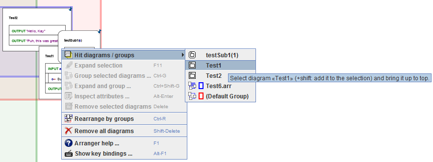
If the status bar checkbox "Show groups" is selected then the submenu will also contain the groups enclosing the current mouse position and offer to select one of them (versions ≥ 3.29-01).
Prerequisites: None (if the mouse position doesn't hit a diagram or group then there will not be a submenu). Expand selection (or <F11>)
Recursively adds all subroutine or includable diagrams that are referenced by some of the currently selected diagrams to the selection set. You will be informed about the number of added diagrams.
Prerequisite: At least one diagram must be selected. Group selected diagrams ... (or <Ctrl><G>)
Creates a new group from the selected diagrams. If there is already a group containing exactly the same diagrams then you will be informed and may decide whether or not to continue. If you continue you will be asked for the name of the group. The group name should ideally be formed like an identifier (i.e. consist of letters, digits, and underscores) but may e.g. also involve dots. Arranger checks whether there is already a group with the chosen name and lets you decide either to modify the name, to merge the selection into he existing group, or to override the existing group if you don't cancel:

Prerequisite: At least one diagram must be selected. Expand and group ... (or <Ctrl><Shift><G>)
Actually combines Expand selection and Group selected diagrams... into a single menu click.
Prerequisite: At least one diagram must be selected. Inspect attributes ... (or <Alt><Enter>)
Opens the Attribute Inspector dialog for he selected diagram.
Prerequisite: A single selected diagram. Remove selected diagrams ... (or <Del>)
This will remove all currently selected diagrams from Arranger. You will first be informed about the number of selected diagrams and be asked to confirm the deletion. If some of the diagrams have unsaved changes then you will be asked whether to save the respective diagram before it is deleted. This may raise an additional Structorizer instance if the diagram had not been associated to the current Structorizer instance or if that currently holds another "dirty" diagram (i.e. with unsaved changes).
Prerequisites: At least one diagram must be selected.
 Rearrange by groups (or <Ctrl><R>)
As the caption suggests, all diagrams will be placed again, group by group. Every group starts to arrange its member diagrams in a new "row" (the icon illustrates this for two groups, a blue and a red group). If a diagram is member of more than one group then it will simply be arranged in the area of the first arranged group out of its associated groups, the group bounds will therefore overlap.
 Remove all diagrams (no key binding, no matter what the pop-up menu tells!)
As the caption suggests, selecting this menu item will wipe the Arranger (after a confirmation request). As before, if there are diagrams with pending changes, you will have the opportunity to decide what to do (save, discard, cancel).
 Arranger help ... (or <F1>)
If you click on this menu item, Arranger will try to open this very User Guide page in the browser. (It cannot check whether the browser may already be showing the on-line User Guide, so on repetetive activation you may get several open browser tabs or instances.) You will be given an information if the User Guide URL wasn't reachable.
Prerequisites: Online connection. Show key bindings ... (or <Alt><F1>)
As before, just tries to open the Key Bindings page, focussed on the Arranger key bindings table, in your browser.
Prerequisites: Online connection.
Saving / restoring Arrangements
Via the button "Save Arr." (before release 3.29 labelled "Save List") in the Arranger toolbar you may save the arrangement of the previously selected subset of arranged diagrams for later re-use. If nothing was selected (or you use a Structorizer version prior to release 3.29) then the entire Arranger content will be saved. In order to save the complete arrangement, you might also press <Ctrl><A> before, thus selecting all diagrams (but now you might possibly exclude some diagrams that are not to be saved by unselecting them with <Ctrl> key pressed).
Alternatively you may select a group being flagged as "modified" in the Arranger index and then trigger the Arranger index context menu item "Save changes".
In general, you have the choice among two options how to save an arrangement:
- To store the mere arrangement list, i.e. a simple text file with name extension ".arr" containing just the file paths and window positions of the arranged diagrams (but no diagram content!) in CSV format. This is a lean text output (CSV = comma-separated values) and intended for local use where the referenced nsd files stay in place. (Of course, the .arr file might be edited manually to adapt file paths of the referred diagrams if necessary.)
- To store a compressed archive with name extension ".arrz" comprising an ".arr" file as mentioned above plus copies of the ".nsd" files of all arranged diagrams. Such an archive is portable to another computer and will exactly conserve the state of all involved diagrams at the moment of saving. The paths inside the archive are relative such that it can be extracted anywhere (see below).
After having pressed the "Save Arr." button or applied the context menu item "Save changes" to a new group, a message box like in the following screenshot will pop up:
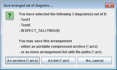
To restore a diagram arrangement from such a saved file you may press the "Load Arr." button (before release 3.29 labelled "Load List") and select either an ".arr" file previously saved or an ".arrz" archive. The file chooser dialog offers file filters for both types. The ".arr" filter is pre-selected but you may switch the filter.
- If you load an ".arr" file but some of the diagram file paths stored in it have become stale in the meantime then the respective diagrams cannot of course be loaded this way (the files not being loadable will be reported in a message box). If some of the diagrams will have been edited meanwhile, however, then obviously the new content will be displayed, not the one they had when the list was saved.
- If you select an ".arrz" file, in contrast, the packed diagrams will always be accessible but they are copies of the original diagrams. If you change diagrams being part of the .arrz archive and save these changes then the .arrz file will be updated, not the original diagrams that had been arranged before the .arrz file was created. If you save a modified group originating from an ".arrz" file then the archive file will be updated accordingly, i.e. diagrams removed from the group will vanish from the archive file, diagrams added to the group will also be added to the archive, and position changes will be adopted as well.
- Arrangement files of both kinds can simply be dragged into the Arranger window. Moreover, you may also load arrangements via the Structorizer itself — either by selecting such an arrangement in the file open dialog or by dragging such files into the Structorizer work area (though the referenced or contained diagrams will be placed in the Arranger, not in the Structorizer). To restore arrangements via the Structorizer has even the advantage that the imported diagrams will be associated with the active Structorizer instance and be pinned.
Hint: you might replace the file name extension of an ".arrz" file by ".zip" in order to "unzip" it with some standard compressor tool (or you could temporarily associate the .arrz file extension with a standard compressor tool as default program). Thereafter you may load the extracted ".arr" file the way described above. This will work while the corresponding uncompressed .nsd files reside in the same directory.
Structorizer tries to associate the file types ".arr" and ".arrz" to it when started the first time but this may not always work with the launcher from the downloadable zip file. With the WebStart installation, however, it should work since version 3.28-05, but still sometimes the attempt fails (or Webstart even fails as a whole). You might establish such an association manually, however, by means of the respective operation system. Typically you will be offered such an opportunity on double-clicking an existing file of the respective type. (Once such an association is established, the WebSart failure will also be gone.)
PNG Export
Via the button  "PNG Export" you can create a PNG file comprising the arrangement of the current diagram selection. As stated in section Zooming above, the current zoom factor is neutralised. If you selected all or nothing then the entire Arranger content will be drawn to file. The dimensions of the exported image are then determined by the maximum of the Arranger window size and the actual bounding box around all arranged diagrams. Since release 3.29, you can export images that contain only subsets of the arranged diagrams. In this case the image will be restricted to the bounds of the selected diagrams and will not show any other diagrams than the selected ones.
Pinning Diagrams
As mentioned in section How to put diagrams into the Arranger, a diagram that had been pushed from a Structorizer instance into the Arranger will reflect all changes the moment it is edited, selected, executed etc. If the diagram is "unpinned" then this dependency even includes replacement, i.e., if you load a different diagram in Structorizer then the related diagram instance shown in Arranger would also be replaced synchronously. To avoid this, diagrams may be "pinned" in the Arranger (select the diagram and then press the "Pin Diagram" button). The pinned mode is indicated by a blue pin icon in the upper right corner of the diagram. For convenience, the pinning is automatically done on pushing diagrams from Structorizer to Arranger. Pinned diagrams still show all changes while shared but are not replaced when you start a new diagram or load another diagram in the related Structorizer instance. The "Pin Diagram" button actually toggles the pin status, i.e. to "unpin" a pinned diagram just press the same button.
Since release 3.29, you may apply the pinning action to an entire lot of selected diagrams. They will first all be pinned if at least one of them had not been pinned so far. If all of them had already been pinned then they will all be unpinned on pressing the button.
Setting Diagrams Test-covered
There is a button  "Set Covered", introduced to support the feature Runtime Analysis. (The button is shown in disabled state in the screenshot at the top of this section.) While the test-coverage tracking mode is activated, you may flag a subroutine diagram parked here as "fully test-covered" such that routine calls to this diagram would immediately be marked as covered even in "deep test coverage" mode (see Runtime Analysis) whithout having to wait until the routine code will actually be covered completely by repeated tests. To withdraw the "test-covered" state just press the "Set Covered" button again — Arranger will simply ask you for confirmation to make sure you didn't touch it by mistake.
Since release 3.29, the action of setting the test-covered flag applies to all currently selected diagrams at once. If at least one of the diagrams has not been flagged test-coverd, then all will be switched into the test-covered state. Otherwise (i.e.if all selected diagrams had already been marked as test-covered) you will be asked for confirmation to reset the test-covered status of all of them. After the action has been executed, the selection will be cleared in order to avoid inadvertent flickering of the test-covered flag on the implicated diagrams.
Arranger Index
As soon as diagrams are placed in the Arranger, the Structorizer GUI (in all associated Structorizer instances, to be more precise) will show a scrollable index tree of the groups and diagrams currently held by the Arranger. It is placed just right of the work area (see figure below, since release 3.30 it shares a tabbed pane with the Code preview in the same place):
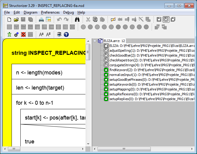
You may switch on or off the display of the Arranger index by key binding <Shift><F3> or menu item "View › Show Arranger Index". While the Arranger is empty, the Arranger index will always be invisible. So, if the Arranger index does not automatically get visible (or the "Arranger index" tab cannot be selected) after having pushed or loaded diagrams to Arranger then check the "Show Arranger Index" status in the Diagram menu.
On the first tree level, the index presents diagram groups, designated by their name and the number of their member diagrams. If a group has been modified, an asterisk preceding the group name will indicate the "changed" status. Registered modifications of a group are:
- addition or removal of one or more member diagrams,
- signature changes of one or more member diagrams,
- location changes of one or more diagrams.
In the Arranger index, three types of groups are visually distinguished by their backing status, each of them symbolized by a different icon:
 A group not backed up by a file (this icon is also used as a general symbol for groups);
 A group originating from or backed up by an arrangement list file (locally bound);
 A group fully backed by a compressed archive file (portable).
Next to the group type icon, a small coloured rectangle indicates how the group bounds will be shown in the Arranger when drawing of group bounds is enabled.
If you expand a group node then the list of member diagrams will unfold on the second level. Each diagram node shows its type icon (main program / subroutine / includable), its signature (name + number of arguments), and file path (if already saved or loaded from file). The member diagrams of a group are sorted by type (main programs first, then subroutines, at last includables) and signature (lexicographically among the diagrams of same type). Diagrams with unsaved changes are marked with an asterisk preceding the name.
Since release 3.29, a "discontiguous" tree selection is supported, i.e. you may select many sequential or isolated nodes. To do so, just do the usual mouse clicks together with <Shift> (contiguous expansion of the selection) or <Ctrl> (toggles the selection of the hit node). Since clicking onto a node has side effects (see below), you may prefer to walk with the cursor keys up and down instead. While traversing with the cursor keys, however, <Ctrl> and <Shift> have a slightly different effect and allow only contiguous selection. Cursor keys <Left> and <Right> as well as e.g. <Numpad-> and <Numpad+> collapse or expand the group nodes, respectively.
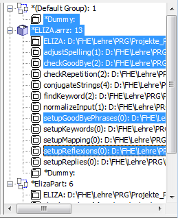
By clicking on one of the diagram nodes (or by pressing the <space> key), the Arranger will scroll to the referred diagram, bring it to top drawing level (if partially eclipsed by others) and highlight it. (This will not modify the zoom factor in Arranger.) So you can identify the diagrams even in case the zoom factor doesn't allow to make out the names of the diagrams. By clicking on one of the group nodes, Arranger will scroll to an area occupied by member diagrams of the group and select all member diagrams there instead of the diagrams selected before. So you could now simply move the entire passel of a group by mouse dragging or by using <Ctrl><up>, <Ctrl><down>, <Ctrl><left>, and <Ctrl><right> keys in the Arranger window.
Double-clicking one of the diagram nodes (or pressing the <Enter> key) will fetch the related diagram and let it replace the one that had resided in the Structorizer work area before. If the diagram to be replaced has pending changes then you will be asked whether to save the changes first. (Provided the diagram is also present in Arranger, the changes wouldn't get lost if you decline, but the risk of inadvertent losses may increase.) Double-clicking a group node will (beside toggling expanded/collapsed status) open an element info box (see below) for the group.
A context menu (see screenshot below) offers specific operations on the groups and diagrams and their relation.
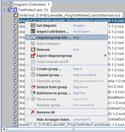
The effect of the menu items and specified accelerator key bindings may depend on the selection. The menu items are explained here:
 Get diagram (or <Enter>)
Fetches the selected diagram and brings it into the diagram work area of Structorizer. If the recent diagram had pending changes, you will be asked whether to save or to discard them.
Prerequisites: Single selected diagram node. Inspect attributes ... (or <Alt><Enter>)
Opens the Attribute Inspector dialog for he selected diagram.
Prerequisite: Single selected diagram node. Diagram/group info (or <Ctrl><I>)
Opens a dialog box with informations about the currently selected group or diagram.
The information about a group includes:
- Name, colour, and number of member diagrams
- Arrangement file path (if persistent)
- Number of shared member diagrams
- Whether there are detected modifications (green or red light):
- whether the set of diagrams has changed
- whether diagram positions have changed
- Whether the group is complete (green light) or incomplete (red light) with respect to referenced subroutines and includables (subtrees will show referenced diagrams that are not member of the group but available in other groups and signatures of referenced diagrams that are missing altogether in Arranger).
- In the button bar you may:
- individually enable or disable the representation of this group in the Arranger tableau (provided "Show groups" is switched on); while disabled, the colour preview will vanish from the icon);
- select the colour of the group among the six available paintbox buttons.
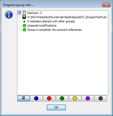
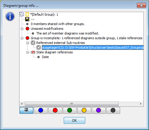
The information about a diagram is a tree with the diagram description as root node and the following sub-nodes:
- Containing groups: the leaf nodes are all groups this diagram is member of
- Arrangement file path (if persistent)
- Called subroutines: the leaf nodes (if any) represent the subroutine diagrams that are directly or indirectly required by CALL elements of this diagram
- Referenced includables: The leaf nodes (if any) represent the includable diagrams that are directly or recursively named in the include list of this diagram
- Stale diagram references: The leaf nodes (if any) name the signatures of subroutines or includables directly or indirectly referecend from this diagram but do not exist in Arranger
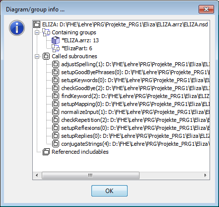
Prerequisite: Single node selected.
 Save changes
All modified groups and diagrams among the selection are saved. As far as they have already been associated to a file, the existing file will simply be updated (synchronized), otherwise you will be requested to choose a file path and — in case of a group — the type of arrangement file (list or compressed archive, see Saving / Storing Arrangements) to be created. Unmodified diagrams will only be saved if they are part of a modified group associated to a compressed archive. Apart from this exception, unmodfied groups or diagrams will not be saved, even if they are selected. Objects that had never been saved, are flagged as modified by definition, so they will be saved after file name and mode are specified unless you cancel the action on that occasion.
Prerequisite: At least one selected node. Test-covered on/off
This marks the selected subroutine and includable diagrams as test-covered if at least one of them hadn't been. Otherwise all of them lose the fake test-covered status (see Setting Diagrams Test-covered for details).
Prerequisites: Only subroutine or includable diagram nodes selected and Executor is in Runtime Analysis mode. (Genuinely acquired test coverage status cannot be withdrawn this way, of course.)
 Remove (or <Del>)
This will remove all currently selected groups and diagrams from Arranger. If both group and diagram nodes are selected then you will first be warned that this might lead to somewhat unexpected results. But you may insist. You will then be informed about the number of selected groups and be asked for your confirmation to delete unshared members of the selected diagrams (you may alternatively decide to move them to the default group, which is effectively what happens on dissolving the group). If a doomed group has pending changes, this will raise the next confirmation box, and you may decide to save or to discard the changes. After all selected groups have been handled you will next be asked to confirm the deletion of the remaining selected diagrams. If some of the diagrams have unsaved changes then you will be asked again whether to save the respective diagram before it is deleted. (This may raise an additional Structorizer instance if the diagram had not been associated to the current Structorizer instance or if that currently holds another "dirty" diagram, i.e. with unsaved changes.)
Prerequisites: At least one selected node.
 Export diagram/group (new since version 3.30-07)
Via the submenu items of this entry you can export the selected diagram or group to any of the supported programming languages (cf. Code Export) or as flowchart file (.pap) for PapDesigner (see Export as flowchart).
In contrast to the export of a single diagram (possibly involving all diagrams recursively called or included), the group export is specifically well suited to create libraries of several routines that do not necessarily refer to one another. All they have to be in order to be exported is members of the selected group.
The file created by group export may contain more than one module, though. So it may have to be cut into separate files at certain marker lines ("scissor" lines, looking like "=== 8< ==="). This is the consequence if there are several mutually excluding entry points in the group, e.g. two or more diagrams representing main programs. In such a case there will usually be a "library module" at the beginning of the file, containing the common prerequisite routines of the different depending modules (which may consist of a main program and several subroutines not shared with other programs of the group) that are appended after a separating "scissor line" each. The export result is similar to that of a batch export of an arrangement file.
Export option "Involve called subroutines" has a slightly different meaning when you export a group: If enabled then referenced diagrams from other arrangement groups may be involved, otherwise the dependency analysis is confined within the selected group. (You will get a warning if certain called diagrams weren't found within the group, though.)
If this menu item is missing in versions ≥ 3.30-11 then this is likely due to an imposed code export/import suppression via a central predominant ini file option (see Code Export Configuration notes).
Prerequisites: Single diagram or single group selected, not in I/O-suppressed mode.
 Create Group ... (or <Ctrl><G>)
Creates a new group from the selected diagram (and group) nodes. Note that if a group node is among the selection then all its member diagrams will be regarded as part of the selection, no matter whether they are individually selected or not. If there is already a group containing exactly the same diagrams then you will be informed and may decide whether or not to continue. If you continue you will be asked for a name of the group. The group name should ideally be formed like an identifier (i.e. consist of letters, digits, and underscores) but may also involve dots. Arranger checks whether there is already a group with the chosen name and lets you decide either to modify the name, to merge the selection into the existing group, or to override the existing group — if you do not back off by pressing "Cancel":

Prerequisite: At least one node must be selected. Expand group ... (or <Ctrl><Shift><G>)
The effect of this menu item depends on the selection:
- Single group node selected: The selected group will be expanded to contain all recursively referenced subroutine and includable diagrams. These diagrams will also remain members of the groups where they were found (shared among the groups).
- Only diagram nodes selected: First retrieves all directly or indirectly referenced subroutine and includable diagrams, then forms a new group from the expanded diagram set. Further details see menu item Create group above.
 Dissolve group (or <Ctrl><#>)
Simply detaches all diagrams from the selected group but preserves the diagrams themselves: Diagrams that are not shared by other groups will be moved to the default group (which will be created if it hadn't existed before). If the emptied group is related to a file then you will be asked whether it is to be removed, otherwise it will be removed automatically. To dissolve the default group is allowed but may not empty it if it contains diagrams not shared by other groups. In the event, diagrams remaining in the default group will definitely be unshared, so to get rid of them you can then simply remove the default group.
Prerequisite: Single selected group node. Detach from group (or <Ctrl><->)
Removes the selected diagrams from their respective owning groups (according to the selected paths). As with Dissolve group, diagrams will not be deleted. If they are not shared by any other group they will be moved to the default group (which is created if it had not existed before). If a group happens to be emptied then it will be removed unless it was related to a file and you declined the confirmation request for its deletion.
Prerequisite: At least one diagram node selected, selected group nodes are ignored. Add/move to group ... (or <Ctrl><+>)
Attaches the selected diagrams to a target group. The choice box for the target group as being popped up is shown in the figure below. You can only select among existing groups (though you are of course free to create a non-empty group via menu item Create group before) with exception of the default group, which is not in the list. Along with the choice you are requested to decide whether the diagrams are simply to be given an additional group membership ("Add to group") or if they are to leave their source group (according to the selected path in the index tree, "Move to group").
Prerequisite: At least one selected diagram node (selected group nodes are ignored). Show group (or <Ctrl><Alt><G>)
Checkbox menu item to enable / disable the visibility of the selected group and its member diagrams in Arranger.
Prerequisite: Single group selected.- Rename group (or <Shift><Alt><R>)
Allows to modify the name of the selected group (versions ≥ 3.29-04). If the group is associated to an arrangement file (list or archive) then you will be offered the option to change the name of the associated file as well.
 Remove All
As the caption suggests, the action of this menu item will clear the Arranger i.e. remove all groups and diagrams (after a confirmation request), and with it the Arranger index. As before, if there are groups or diagrams with pending changes, you will obtain the opportunity to decide what to do (save the diagram(s), discard the changes, cancel the action). Eventually you will be informed that the groups have been emptied and you will be asked to confirm that they may also be removed. It is not recommended to let them stay with the pending changed status, because if you accidently save all changes you woud empty the associated files, too.
- Show qualifiers as prefix (since release 3.31)
In case of diagrams imported from OOP languages like Java or Processing, a package or namespace qualifier might be associated to eahc of the diagrams. If this checkbox menu item is selected (the default) then the node text will show the entire qualifier path as name prefix. If you unselect it then the diagram nodes will be arranged in a multi-level tree according to their namespace relations (member classes/methods als children of their containing class node). This may reflect therelations even better but requires more synchronisation time on routine pool changes, the frequent tree updates might induce a heavy GUI contention. So use it with care. For ordinary diagrams this setting has no effect at all.
- Hide Arranger Index (or <Shift><F3>)
As the caption says, this is just another way to make the Arranger index temporarily invisible.
You may reduce or enlarge the width of the Arranger index viewport simply by moving the divider rightwards or leftwards. As already mentioned, you may hide the Arranger index entirely by unselecting the menu item "View › Show Arranger index?". Alternatively, you may also toggle the index visibility with keystroke <Shift><F3>.
Diagram work area, Arranger index, and Analyser report list form a focus ring where you may navigate by the <Tab> key in clockwise and by <Shift><Tab> in counter-clockwise direction. Since many actions force the focus back into the working area, the Arranger Index changes its background colour when it gains or loses focus. While the focused colour depends on the selected Look & Feel (usually white but may also be e.g. dark gray), the unfocused colour will always be the light gray shown in the figure above. So you will be aware whether the Arranger index has the focus or not. This may be important for the effect of overloaded key bindings.
Note: If you have changed the Look & Feel while the Arranger index tree was visible, problems may arise, e.g., it might no longer react to some menu items or key bindings. (In versions before 3.29-03, the context menu might have shown duplicate icons etc.) In such a case save all changes and start Structorizer again. Then the Arranger index will be working correctly with the chosen Look & Feel.
7.9. Find & Replace
If you have to deal with a significant number of diagrams, powerful editing capabilities get essential. You may want to search for diagrams and elements containing certain substrings and to perform consistent changes (e.g. variable renaming) even throughout several diagrams.
The Find & Replace dialog offers a variety of helpful selection and modification opportunities in various combinations:
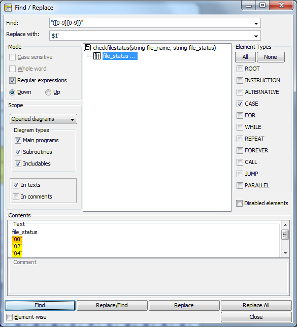
Activation
There are several ways to open the File & Replace dialog:
- by pressing the speed button
 in the toolbar;
- by entering the accelerator key combination <Ctrl><F>;
- via the Edit menu:
Find and Replace Patterns
At the window top you enter your textual search pattern, either interpreted as plain substring or as regular expression (depending on whether or not checkbox "Regular expressions" is selected).
Beneath the search pattern you may enter a replacing string or pattern if you intend to substitute one or more of the found substrings. If the Regular expressions checkbox is selected then the replacement may contain placeholders like $1, $2 etc. which refer to the content of the first, second and so on group of the regular expression match. (A group in a regular expression is a sub-pattern in parentheses, like ([0-9][0-9]) in the screenshot above, which would mean $1 to be 00, 02, 04, respectively, for the first, the second, and the third match).
The Find & Replace dialog keeps a history of depth 10 for each of the two pattern fields, which is available via the respective pulldown button.
Mode settings (left-hand side)
Here you may specify the search direction and how the patterns are to be interpreted.
Direction "down" means to traverse the search results from top to bottom and the matches within a single text in forward direction. Direction "up" is the opposite (bottom to top, from right to left).
The checkbox "Regular expressions" specifies — if selected — that the patterns be interpreted as regular expressions with exactly the syntax accepted by Java class java.util.regex.Pattern. Since a complete description would exceed the scope of this user guide, just some examples:
| Pattern | Matches | Examples |
| b.y |
All three-character substrings starting with b and ending with y |
bay, boy, buy |
| b.?y |
Substrings with at most one character between b and y |
by, buy, b2y |
| b[a-z]*y |
Substrings with any number of lower-case letters between b and y |
by, bay, buoy, baby, belly, balcony |
| b[a-z]*?y |
Substrings with minimum number of lower-case letters between b and y |
the ones before except baby (where by is the smaller match) |
The checkboxes "Case-sensitive" and "Whole word" are only selectible if "Regular expressions" is unchecked. Regular expressions may specify themselves whether case matters or how a substring be surrounded in order to match, though with some effort — in order to match the word "result" case-independently and as isolated word, you might write the following regular expression:
(^|\W)[Rr][Ee][Ss][Uu][Ll][Tt](\W|$)
In plain-string mode, case does not matter by default, and the pattern may be any substring, such that a search string BY would be found within Babylon.
By selecting any of the checkboxes "Case-sensitive" and "Whole word", however, the above word would no longer be a match.
Scope settings (left-hand side)
You may choose the search scope among
- Opened diagrams = all diagrams currently held in Structorizer and Arranger,
- Current diagram = just the current diagram in Structorizer (Arranger not searched), and
- Current selection = just the currently selected sequence of elements in the current diagram, including substructure.
If you opt for all opened diagrams then you may restrict the search to certain diagram types (i.e. any subset of them).
Further on, you may specify whether the element texts and/or the element comments are to be involved in the search. (To exclude both doesn't make sense, of course.)
Element types (right-hand side)
You may limit the search to any subset of element types, e.g. to exclude Call elements from search. The All and None button are to facilitate selecting or unchecking all element types at once.
Independently of the element type choice, you may or may not include disabled elements.
Result view (central)
When you have specified all search criteria according to the opportunities explained above, pressing the "Find" button will start the search.
The central view will show the tree (or "forest") of all found elements in the diagrams according to the scope setting. The diagrams containing elements with matches form the forest roots, the found elements are the subnodes (leaves) of their respective parent diagram. All elements with matches in texts or comments appear at the same level, no matter how deep they were structurally nested. If you don't see elements below a diagram root then just click on the respective root in order to expand the subtree. If the diagram header element itself holds a match then it will also be shown at the element level. In forward mode, the first matching element (in the first presented root) will already be selected and its text and comment appear in the contents text areas at the dialog bottom. If there are several matches within the enabled text areas then all but one are highlighted in yellow, the very current match within the text has orange background (see figure above).
The further navigation depends on whether checkbox "Element-wise" (in the lower left corner next to the buttons) is selected or not: If not then the next click on "Find" will move the orange spot to the next match within the text of the same element, if checked, however, the presentation skips to the next element from the result list ("fast" mode).
You may change navigation direction by switching the radio buttons "Down" and "Up", thus going back to previous matches.
While you traverse through the elements, Structorizer will simultaneously scroll through the current diagram and highlight the current element if the element belongs to the diagram in the work area. While you traverse elements of other diagrams in the result tree, Arranger will scroll to the respective diagram in its arrangement.
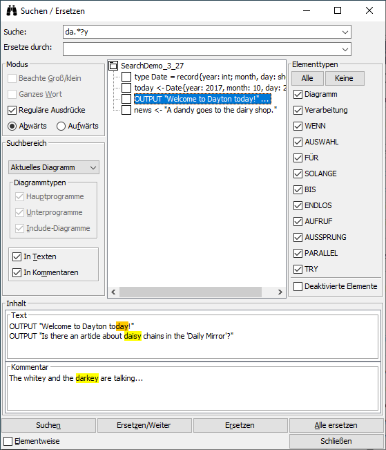
Buttons
The Find button starts search (if result view was empty or exhausted) or moves the spot to the next/previous match within the text of the current element ("Element-wise" off) or to the next node of the search result ("Element-wise" on).
Button Replace/Find will replace the currently focussed match and then move to the next match the way the Find button would do. Be aware that doing the replace action with empty replace pattern field will delete the matching substring.
Button Replace just replaces the spotted match without moving the spot afterwards.
Button Replace All will blindly replace all remaining matches from the currently selected match on towards the end of the search result set in the specified navigation direction (down/up). So it doesn't always really mean "all".
Every single replacement is undoable (and redoable) in reverse order, but only from the respective diagram, which must be summoned to the Structorizer window. The undo / redo action or any other editing in the diagram will wipe the result tree in the Find & Replace window. So does any diagram addition or removal in the Arranger if scope "Opened diagrams" is selected.
The Close button will simply hide the Find & Replace dialog, all settings will be maintained and will still be present on reopening the dialog. Most criteria and the pattern histories will even be saved in the structorizer.ini file on ending the session such that they will be restored in the next Structorizer session.
Mnemonics
The four main buttons and several other mode-relevant controls are associated with mnemonic keys, such that pressing <Alt>+mnemonic has the same effect as clicking the respective control. Version 3.29-11, however, modified some of the mnemonics (particularly that of the "Down" radio button) and equipped more controls with mnemonics. The underscores (becoming visible on holding the <Alt> key down, with some Look & Feels they are constantly shown) in the screenshot below demonstrate which mnemonics are configured for the English locale (may differ slightly in other locales, cf. screenshot with German locale above) since version 3.29-11:
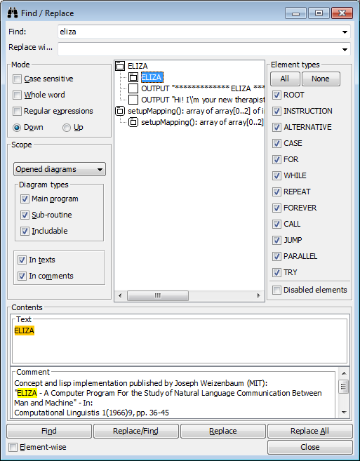
Known problems
In rare cases, particularly with regular expression mode and large multi-line texts or comments in some elements, the regular expression mechanism may apparently run into a Java-internal endless recursion crash, which results in an awkward dialog state, often noticeable via rendering defects on icons and text font in the result area (as if the dialog elements were disabled), e.g.:
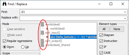
Usually, the dialog will still react and return to full function with the next (different) search.
7.10. Content Assist
Version 3.32-11 brought a long missed innovation: a Content Assist for the element editor text area. It offers autocomplete functionality.
When you type element text (as described on the Elements pages) then the Content Assist will propose you command keywords, names of declared variables and constants, and other sensible word suggestions that match the entered characters as prefix. The suggestions may depend on the type of element and the caret position. When you e.g. edit an Instruction text and the caret is at the beginning of a line then the keywords for input and output instructions as configured in the Parser Preferences will be among the offered choices:

The screenshot shows that the matching is case-ignorant.
Via the "Suggestion threshold" spinner at the right-hand side above the text area of most editors you may specify the minimum length of the prefix that triggers suggestions in a pulldown list. The value may be in the range of 1 through 5. By choosing 0 you may switch off the Content Assist. If you choose e.g. 2 (the default) then the second typed character (that is allowed as part of an identifier) will instigate Content Assist to pop up a pull-down list of the matching relevant words (if there are any). In the following screenshot the variable names starting with the typed prefix "da" will be presented:
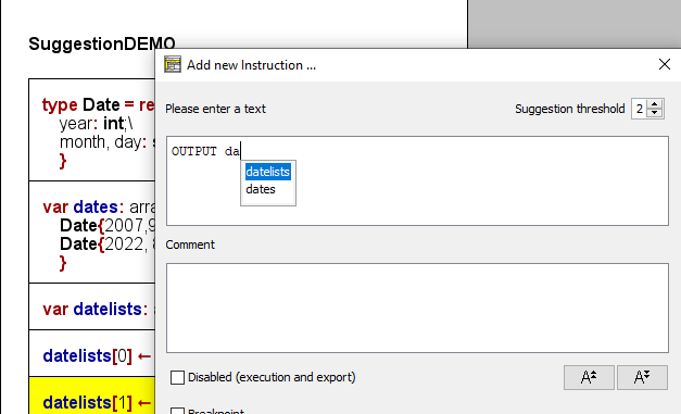
In order to accept one of the proposals just select it (by <↑> / <↓> keys) and press the <Enter> key. This will insert the chosen word at the current caret position (replacing the matching prefix if case differs). If you regret the choice then you might simply undo it (<Ctrl><Z>) or delete as many of the inserted characters as required to let Content Assist offer more proposals again. If you don't want to adopt a proposal then simply go on typing and ignore the pulldown list. The pulldown will vanish as soon as no matching words are avaible.
At the beginning of EXIT (Jump) element lines the three configured command keywords for leaving a loop, a routine, or the program are offered as well as the keyword for raising an exception. One of them must have been placed at the beginning of the text before variable names or other relevant content will be proposed.
In a CALL element the signatures of the currently available subroutine diagrams are among the choices:
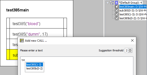
If you insert one of the offered subroutine signatures then it will alter its representation a bit: Instead of the argument number a formal argument list will be presented that contains a question mark at every mandatory argument position and just an ellipse for all optional arguments together:
Of course, Content Assist is also active on editing existing elements. (You may just have to alter a word in order to get content suggestions.)
If you place a dot after some variable construct and Content Assist manages to infer the data type of the preceding syntactic construct and it happens to be a record variable then Content Assist will offer all component names of the specific record type (you may of course narrow the choice by typing further characters):

Content Assist also tries to help with type definitions and variable declarations:
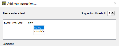
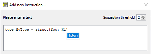
The depth of the syntactic analysis is limited, however, so with complicated structures the autocompletion suggestions may be of lesser benefit. Yet in most standard situations it should accelerate the input of the element text significantly and encourage the use of longer and expressive variable names.
Remark: The Content Assist is also attached to certain form fields in specialized element editor variants like that for FOR loops:
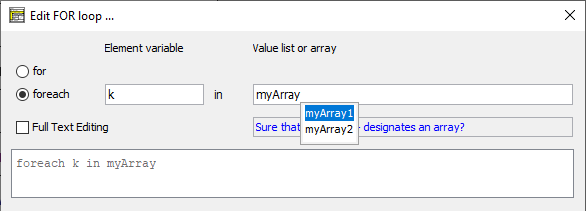
7.11. Translator
What is it?
The Translator chiefly is a tool to facilitate the maintenance of the application itself but also offers customisation opportunities.
As you probably know, Structorizer GUI is available in different languages. The small developer team alone, however, is only capable of keeping about three translations up-to-date: English, German, and Spanish.
But you may help! Users with a good understanding of the concerned concepts and mastering one (ore more) of the likewise neglected languages are invited to help keep the other localizations consistent and up-to-date. Even small steps improving the translations are welcome. We promise: You will not be held responsible for missing translations or misspellings or whatever. They will simply be corrected the next time. This way, a very appreciated external helper from the Netherlands pushed the Dutch translation forward to near completeness, lately.
To facilitate user's contribution, Structorizer integrates a component called "Translator" in its GUI. It allows easily to edit the different translation sets. The translations can be saved, reloaded and resumed, and last but not least, you may even induce a preview of your current translation in Structorizer, which makes testing a lot more user-friendly than it had been before.
Translator is opened via the menu item "Translator ..." in the "File" menu of Structorizer:

How does it work?
Translator GUI comes with a toolbar and a tabbed table view.
The toolbar consists of language buttons (each showing a flag), a question mark button, a preview button (showing an eye) and a button to save an edited translation to a file.
The table view will initially be empty and show nothing but a message "Please load a language!":

By pressing one of the flag buttons you will select and fetch ("load") an already supported locale. To create a new translation click on the button showing the question mark.
By keeping the <Shift> key down while clicking on a language button you can load a previously saved local translation file instead of the currently installed translation. Since version 3.30-16, the icons of the locale buttons will temporarily change (small folder symbols will appear over the flags) while you hold the shift key down, in order to indicate the altered mode:

Moreover, you get a context menu on each language button (including the "question mark button") offering you the different button-related load/save options in another way:
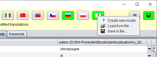
Why isn't there a single load button? Well, could have been, but the idea is to use the locale-specific button, because this allows the comparison of the product locale with your modified file — all differences will be highlighted. For completely new language projects, it does not of course make sense to highlight all differences to a different language. Therefore the "Create new locale" button now also offers the option to load a begun translation file without highlighting all entries. Only the changes with respect to the content when loaded will be tracked, which maes most sense.
At any time you may freely switch to another language to check or compare other translations (e.g. in order to disambiguate or to help your understanding) without losing your changes.
Now you will be presented the translation contents in several chapters selectable by the tabs:
- Header (representing the language file header with explaining comments and change history);
- Structorizer (translations for the core product GUI);
- Arranger (translations for GUI of the Arranger component);
- Executor (translations for the GUI of the Executor component);
- DiagramController (translations for diagram-controllable modules like Turtleizer);
- Elements (optional localization of the element type names, also see Element Names Preferences);
- Keywords (optional localization of Parser Preferences).
Each of the tabs (except the Header tab) shows you a scrollable table of three text columns (plus a fourth column holding pull-down buttons):
- Key string (dot-separated hierarchic sequence of component identifiers or numbers, possibly followed by a bracketed condition);
- English caption or text (as far as available);
- translation in the selected language (as fas as available) — this column is the only editable one.
By double-clicking the cell in the the third column, you may edit its content. In some cases the messages may be very long, such that editing within the table cell may get very cumbersome. The pull-down button in the fourth column (at the end of each editable row, introduced with verson 3.29-11) address this problem: a specific translator row editor will open, offering more comfort. It is described further below.
The Translator highlights what work has already been done (i.e. all differences w.r.t. the locale delivered with the product version) and which translations are still missing.
Highlighting colours:
- Cyan-coloured rows having a string enclosed by "-----[" and "]-----" in the first column represent a section name and cannot be edited. They just group entries belonging together.
- Missing translations in editable rows are highlighted in orange. Note that in certain cases the English translation may also be absent due to missing necessity (e.g. in cases of one-way dialogs or file extension names), as shown in the screenshot above. This does not mean, however, that a localization is not necessary. If you don't have an idea what text it should contain then just contact the developer team, please.
- Translations added or modified w.r.t. the delivered locale are highlighted in green (only in the last column).
- If a translation was deleted (in comparison to the delivered locale) then the respective entry will be hightlighted in red (only in the last column).
On selecting a row, the background colours vary to emphasize the selection:
Changes are cached but not automatically saved to file. As soon as a language set contains at least one modification, the respective language button will show green background, therefore, to indicate unsaved changes. So it is easy to stay in control and keep track for what languages there are unsaved changes. (With some look & feels, however, this button colouring may hardly be detectable. You may try with a different look and feel then, controlled by the look & feel preference of Structorizer, "Nimbus" should usually do well.)
Filtering
Since version 3.31-03, you will find a group of three radio buttons for filtering between the locale buttons and the section tabs:
- Show all rows
- Only missing translations
- Missing and modified translations
The radio button group allows you to restrict the presented rows to those that are still empty for the currently selected locale (see screenshot) or the empty ones plus all modified ones. This allows to efficiently accomplish a translation without the need to scroll through large tables on end. Subsection headers will always be visible, though, for better orientation.
In filtered mode, to fill in a missing translation will not make the row vanish immediately, though. In order to hide the already filled rows switch to another filter option and then back. This induces an update of the filter result.
When you change the locale (i.e., load another locale) then the filter will be reset (→ "Show all rows").
Be aware that an active filter also affects the search scope (see below).
Placeholders
Mind the placeholders in the texts. These are meant to be replaced by variable strings at run time. There are three kinds of place holders:
- Ordinary ones, starting with a percent character: "%", "%1", "%2", etc.;
- Element name place holders, starting with '@' and followed either by a single lower-case letter or an internal element class name, enclosed in braces: "@a", "@b", "@{For}";
- Indexed placeholders "[#]" to be substituted by the current index for array targets.
If place holders of these kinds appear in an English master text then they should also be put at appropriate positions (according to the grammar requirements) into the respective translation texts. Read more about the element name place holders (introduced with version 3.27-04) in section Preferences => Element names. Note that the translator row editor (as introduced with version 3.29-11) allows you a preview of the element name placeholder substitution.
Search
You may search for a certain substring in the currently presented table (since version 3.27-04). The "Find" dialog is opened by pressing key combination <Ctrl><F> (as usual):
The use of the Find dialog is quite straightforward: Enter the substring you are looking for, select the column numbers (with regard to the currently shown table) you want to restrict your search to, decide whether the search is to respect letter case or not, and press either the upwards or downwards button (the ones showing a blue triangle). Then the previous or next line containing the given substring wil be leaped to and selected. This should help you preserve translation consistency.
Note: If a row filtering is imposed (versions ≥ 3.31-03, see above) then only the visible rows will be searched. Consider switching to "Show all rows" before starting the search if all entries of the current table are to be scanned.
As mentioned above, you may arbitrarily switch to another locale (e.g. for comparison) without losing your changes, simply by pressing the respective language button (or by pressing the <Enter> key while the button has the focus). If you click on the language button of the very locale you are currently working on and there are cached modifactions for this language then you will be asked if you want to discard the changes. If you agree then the original locale will be reloaded. If you decline then nothing will happen (the button action will be cancelled).
On closing the Translator, however, you will be warned if there are unsaved changes for some of the languages. You better save them before or at least now. If you re-open Translator without having closed Structorizer, however, the changes may still be present. Caution: You won't be warned of unsaved Translator changes when you close the owning Structorizer (i.e. the entire application)!
Translation preview
To preview the modifications in the currently running Structorizer, press the "eye" button  in the toolbar (also see images above). The Structorizer GUI will immediately be retranslated with your locale. In Structorizer itself, the language preference menu will indicate this situation as follows (since version 3.30-13):
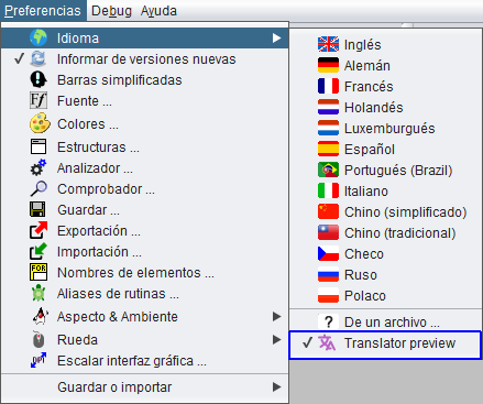
You cannot switch off the preview in Translator itself. Instead you should select a regular locale in the language preference menu of Structorizer shown above. Alternatively, you may switch to another language in Translator and activate the preview button again, which is just a different preview, actually.
How to save translations
In order to save the translations of a language including all cached modifications for it into a file, make sure the respective language is selected (look e.g. at the header of the third table column) and then press the save button — it's the rightmost button of the toolbar, showing the usual floppy disk symbol. (You might have to enlarge the window to access it, cf the images above where only a section of it may be visible.) A file selection dialog will pop up and allow you to choose a target folder and — if wanted — a differing file name. If you happened to conduct modifications for several languages then each translation file must be saved separately. After having saved the changes, the associated language button colour will not return to the default button colour (usually some shade of gray) but turn pale green, indicating that all changes will stay cached:

This way, you may continue modifying the translations without having to begin from start. Any new modification will turn the button background to bright green again, of course.
How to load translation files
You may (re-)load saved translation files for a locale into Translator in order to resume with the result of a previous session. To do so hold the <Shift> button down while you click on the appropriate language button.

This will switch to the respective locale and open a file selection dialog allowing you to choose a translation file for the selected language from the file system. The translations found in this file will be loaded into Translator (for the selected language). All differences to the original locale will be highlighted as if they were just edited (see description above). The heading of the last (third) column (in every tab) will show the file path together with the locale name, e.g. "es (/usr/home/mickey/language_files/es1.txt)". If there had been unsaved changes for the selected locale before you clicked the button then Translator will first ask you whether you want to discard them (which is prerequisite for — or side-effect of — loading the file); by declining you cancel the loading action (nothing will happen). So if you'd rather save the changes you should cancel the overloading, save the pending changes and then try to load the file again.
Be aware that Translator does not check whether the loaded file actually belongs to the selected language or not. If not, then nearly all entries are likely to be marked as changes, of course. The button with the question mark, however, allows you to load translation file (labelled "extern (<filepath>)" then) whithout highlighting all fields as different. Only modifications after having loaded (or last saved) the file will be highlighted.
Note: New releases might change some message keys or slightly modify structure and hierarchy of the translation packages. So if you load a file originating from an earlier Structorizer version you may see several regions highlighted in red, i.e. as deletions, whereas some translations may not be displayed (though possibly being present in the file). If you know what you are doing, a manual modification of the keys in the text file according to the ones shown in Translator may help avoid losses. (But if it happens to be a lot of eclipsed new text then you may dare open an issue in the GitHub project and attach the outdated file, in order to let the development team sort it out — we know the mappings, of course.)
How to use an individual translation
Note also that saving a translation file does not mean that your local Structorizer installation would automatically use your modified translations from now on! You may force Structorizer to use a modified language file explicitly, however, by choosing the " From file ..." menu item in the language preferences menu: The path of the loaded file would even be kept in the structorizer.ini file and hence automatically reloaded on the next start — until you select another language.
As already stated in the introduction, however, the Translator tool is chiefly meant to facilitate the maintenance and usability improvement of the Structorizer product. So the best you can do is to send an accomplished translation file in after having tested it by the preview tool) as requested under the IMPORTANT note in the header part of each translation file. (Don't forget to add a description of your changes to the Revision list section of the Header chapter.)
Last, but not least, you may create a translation file for a "new" idiom — meaning a language not having been provided so far by the language preferences. To do this, simply press the "?" button in the toolbar instead of one of the flag buttons. This way, you may start a completely new translation from scratch, i.e. with an empty third column. Just fill in the Header chapter appropriately, i.e. specify the language and yourself as author etc., and send the file in after completion. The Structorizer team will be grateful for your help.
Translator Row Editor (since version 3.29-11)
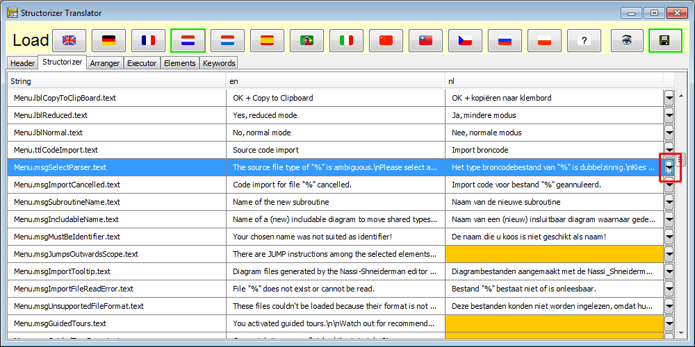
The button in the last table column (see screenshot above) opens a translation editor for the selected table row, showing the key (and possible conditions presented in a table for better readability), a text area with the English default text (from the second column), a text area with the translated text for the currently selected locale, and a third text area where the respective text of a selectable comparison locale can be presented.
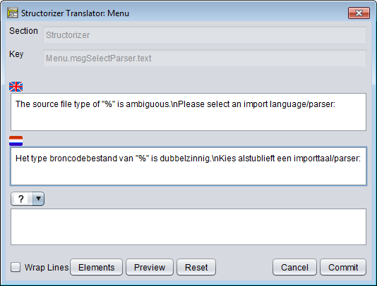
The checkox "Wrap Lines" allows you to switch between symbolic newlines (escape character sequence "\n") and real newlines:
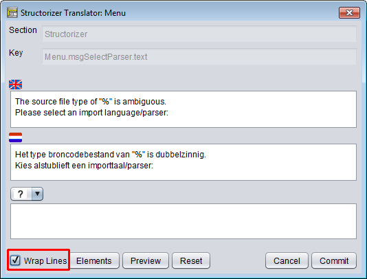
Via the pulldown choice element "?" between the second and the third text area you may select a third language for a reference translation:
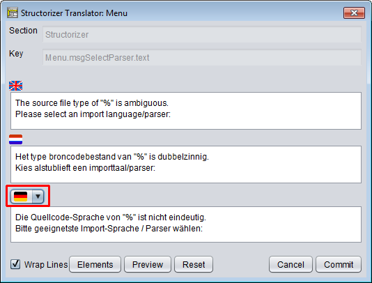
If you activate the row editor for a line with conditioned key then the conditions will be presented in a table at top:
The "Elements" button pops up a window, which is listing the available element type name placeholders in short and long form as well as the corresponding translations in the default locale (English), your selected locale, and the most recent comparison locale (so you will not have to leave the row editor in order to look up the placeholders in the header tab):
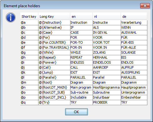
By means of the "Preview" toggle button you may have the element type name placeholders in the currently presented texts replaced by the respective element name localizations until you press it again (deselect it). During preview mode, editing is not possible:
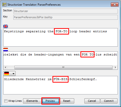
Undo/redo stacks haven't been implemented in the text area, but you may undo all current changes without leaving the dialog by pressing the "Reset" button. The same effect ist achieved by pressing the "Cancel" button but that it closes the dialog. Eventually, the "OK" button will commit your changes, copy the resulting translation into the related table row and close the dialog.
8. Settings
The settings are (in their majority) related to diagram properties or modes to display diagrams and therefore available in the "View" menu (before version 3.32-13 it was the lower part of the "Diagram" menu). Additionally, some of them can be controlled by toolbar buttons, accelerator keys, context menu items etc.
8.1. Unframed diagram?
This setting is available via the "Diagram" menu:

The setting influences the way a specific diagram is drawn. Boxed (framed) diagrams are somewhat larger because there is a special box drawn around the inner elements. Non-boxed (unframed) diagrams are reduced in size, obviously.
The heading (and a lower margin for diagrams of type sub or includable) of a non-boxed diagram is gray whereas the box around a boxed diagram is white:
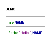 |
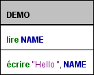 |
| Boxed diagram |
Un-boxed diagram |
For further details about this, please look here...
Whether diagrams are presented in boxed (framed) or un-boxed (unframed) style has no impact on execution or code export.
Note that this is not a general view mode affecting all diagrams at once but an individual property of every single diagram. At the same time some diagrams may be unframed while others are boxed. The property is stored with the diagram.
8.2. Show comments?
Normally, the comments attached to the elements are not visible in the diagram, unless you open the editor for an element or activate mode "Comments plus text".
Mode "Show comments?" makes comments visible on demand only and therefore induces two effects:
- Commented elements are marked with a vertical gray bar along the left edge.
- While the cursor hovers over a commented element (indicator see above), the comment will pop up as tooltip. (Note: Very abundant comments may induce a rapidly intermittent popup behaviour while the cursor is hovering over the respective element.)

To enable / disable the comment mode use the menu item "Show comments?" in the menu "View" (before version 3.32-13: menu "Diagram"):
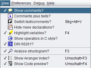
Completely different ways to show comments are offered by modes "Switch text/comments?" and "Comments plus texts?".
Note that mode "Switch text/comments?" inverts the mechanism of both the gray marker bars and the tooltips: The gray bars will then indicate elements with non-empty text fields, and the tooltips will show the text instead of the comment (which is then drawn in the diagram).
8.3. Comments plus text?
Display mode "Comments plus text" allows you to render, print, and export diagrams with the elements showing both comments and texts at the same time:
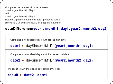
The comments are written in somewhat smaller font above the actual element text. Of course they enlarge the diagrams. Due to the triangular form of IF or CASE element headers, the impact of including large or many comment lines could easily get optically desastrous if the shape weren't be modified a little — the sloping edges of the head triangle begin only below the comment such that it is no longer a triangle:
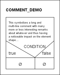
The mode "Comments plus texts" can only be switched on or off via the menu "View" (before version 3.32-13 it was placed on the lower half of menu "Diagram"):
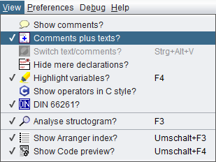
Note that activating mode "Comments plus text" disables the display mode "Switch text/comments" and suppresses its effect until the mode "Comments plus text" will be switched off again (by toggling the menu item). A previous setting of "Switch text/comments" remains preserved, though. The disabled menu button will only show a tooltip explaining what do do in order to reactivate the controls of "Switch text/comments".
Here are some more examples of diagrams in mode "Comments plus text":
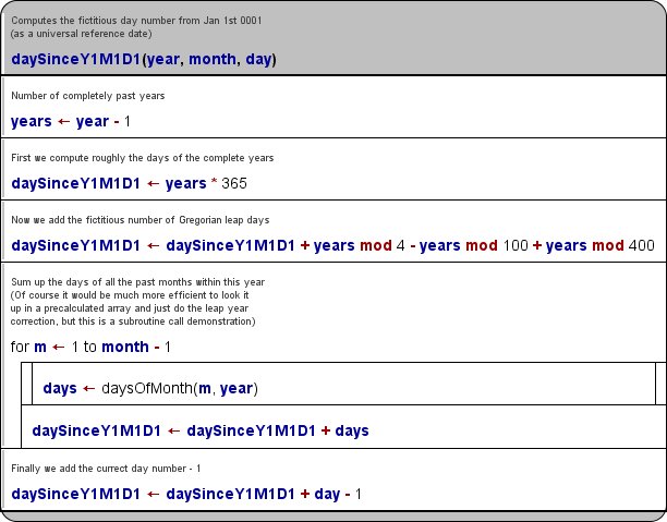
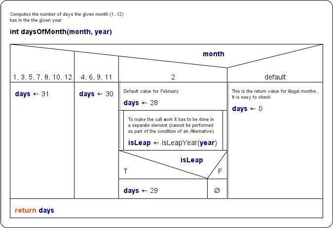
8.4. Switch text/comments?
Effect
Mode "Switch text/comments" just swaps the visible content of the diagram elements: Where usually the instruction text is displayed now the comments of the elements are shown, whereas the actual element content is only popped up while the cursor hovers over the respective element (provided, mode "Show comments" is active).
Motivation
Algorithm design may start with the structure and just some verbal specification of what is roughly to be done in the instruction block or loop etc. And this rough sketch is later to be refined by more formal expressions.
If the refinement replaces (und hence drops) the specifying descriptions they would get lost. Instead they might serve as useful comments and to compare the implementation with the specified intension. They would have to be copied from the text field to the comments field in the refinement phase, which is feasible but cumbersome. So why not start with them as comment in the first place? Well, because the diagram would look bare and empty until the "real instruction code" be filled in:
And that's where the "Switch text/comments" mode fits in. You can enable/disable it in the "View" menu (before version 3.32-13: "Diagram" menu):
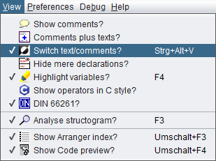
(Note that the menu item may be disabled. This will be the case while the mode "Comments plus text" is active, which has priority. On the other hand, while mode "Switch text/comments" is active, the access to menu item "Operators in C style" will be blocked as to be seen above.)
In mode "Switch text/comments", the diagram elements display their comments instead of the "code" text. So you can design and document an algorithm just based on the informal comments:
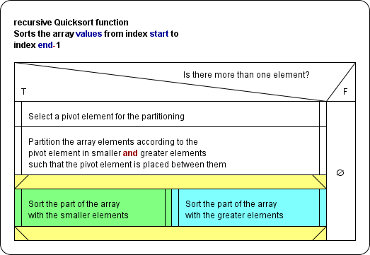
This comments display mode documents the design at an abstract level, and all the information will stay in place (i.e. in the comments sections), even after the actual code had been filled in (to the text sections). Thus it will remain reproducible whenever you "switch" to this mode again.
You can edit the elements where both text and comments are available in the editor forms, specifying the code details. When you are done (or whenever you like) you may switch back to normal mode in order to see the "implementation":
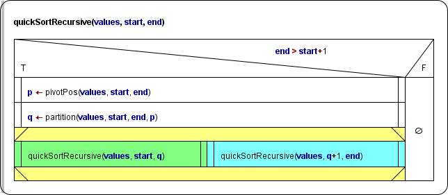
Thus you may switch between both modes whenever you want, according to the emphasis you put on.
Impacts on and interference with other functions
The "Switch text/comments" mode sensibly modifies the way mode "Show comments" works: If both modes are combined, the comment indicator bars will show where there is already an implementation. Consequently, it's the code (text) that will pop up while the cursor is hovering over an element:
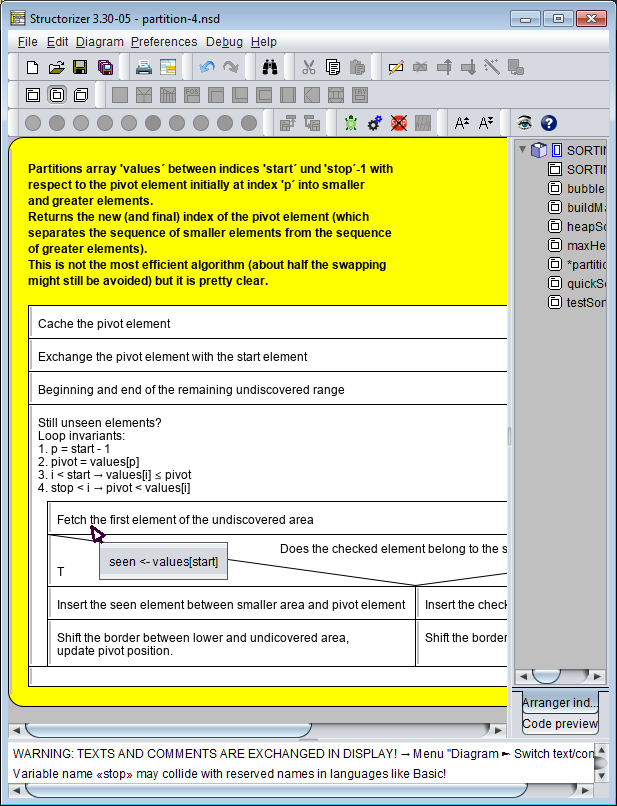
Since version 3.30-14, the content of the popups will be presented as styled text while the display mode "Highlight variables?" is also active (in this case display mode "Show operators in C style" may additionally impose modifications to the text):
On opening an element editor (see Edit element) it depends on the "Switch text/comments" mode whether the initial focus (the cursor) will be in the text area or in the comment area — it's the one presented in the diagram (with rare exceptions).
The static Analyser will present a warning in the Report List while the "Switch text/comments" mode is active, such that unexperienced users won't panic if they see their diagram suddenly empty:

Since version 3.30-11, there is an additional mode indicator in the toolbar (e.g. for the case that the Analyser Report list is disabled) - see red circle below:
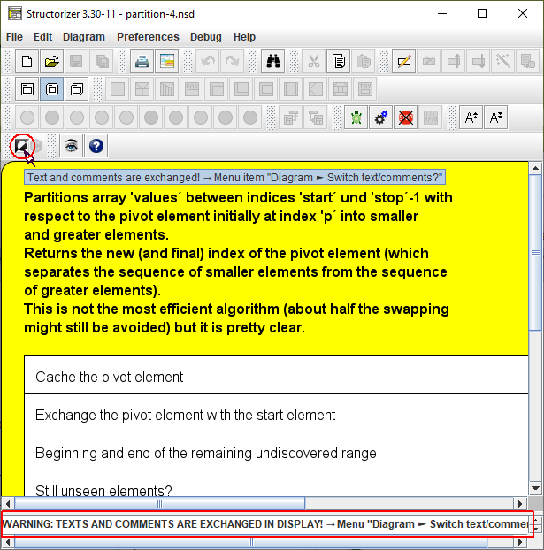
Note that this display mode will be suppressed while mode "Comments plus text" is active.
8.5. Hide declarations?
The data-descriptive power of Structorizer has been enhanced significantly in the most recent years (e.g. record type definitions, constant definitions, mere variable declarations, possibly even method declarations). On the one hand, this was helpful in modeling more meaningful algorithms and particularly for source code import with as little losses as possible.
On the other hand, all this descriptive power to be placed in Instruction elements may quickly grow to occupy major linear parts of a diagram, this way distracting attention from the actual algorithm structure:
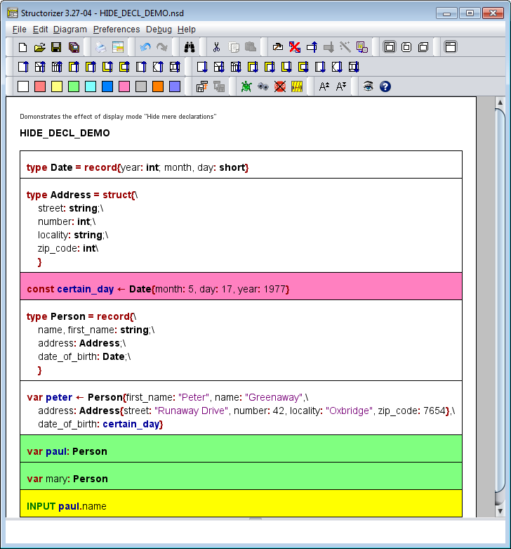
To get back to the roots, i.e. to the original purpose of a Nassi-Shneiderman diagram, you might of course delete all the declarative parts but this way you would lose or at least compromise the possibilities of debugging (execution) and sensible code export.
Now, version 3.27-04 brought the remedy: A display setting "Hide mere declarations?" was introduced, allowing you to hide most of the declarative stuff without removing it. You find the respective checkbox menu item in the menu "View" (before version 3.32-13 it was on menu "Diagram"):
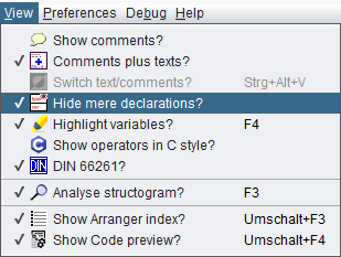
Similar to collapsing complex elements, an entire sequence of mere descriptive stuff (type definitions and variable declarations without initialization) will then only be represented by a surrogate (placeholder) element looking exactly like a collapsed instruction but with a specific icon:  (which is the same as in the menu item). Structorizer automatically detects the maximum extension of declaration sequences. In contrast to collapsing, however, this is not an element-individual modification but a global display setting (like comment display modes), i.e. it affects all declaration parts throughout all diagrams at once. To enable or disable this mode has absolutely no impact on the diagrams themselves.
Constant definitions and variable initializations (i.e. assignments), however, are not regarded as mere descriptive elements, since they induce material processing steps when reached on execution. Hence, each declarative sequence ends (is interrupted) at any constant definition or variable initialization (like at regular immanent algorithmic structures):
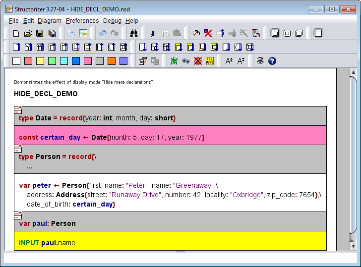
Note: On editing a diagram be aware that the surrogates of declarative sequences represent them as a whole, i.e. if you delete or move a surrogate, this will always affect the entire sequence hidden behind it! If you add a new declaration element directly after or before such a surrogate in mode "Hide mere declarations?" then you shouldn't expect to see this new element because it will immediately be hidden as well. In case you inserted it before the former surrogate, however, it will take its place, i.e. its first line will now appear as visible surrogate content.
8.6. Highlight variables?
Generally, all text in the diagram elements is written in standard font (black), but you may enable the option "Highlight variables?" in the menu "View" (before version 3.32-13 it was in menu "Diagram"). This does not only highlight variable names, but also operator symbols, string and character literals, and certain keywords (also see page Syntax highlighting in the Features section, page Parser Preferences, and page Controller Aliases):
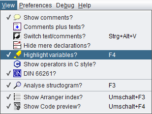
Alternatively, you may press <F4> to toggle the highlighting mode.
Note that with highlighting mode switched off, the menu item beneath it, "Show operators in C style?" (as introduced with version 3.30-11) will be disabled because it would not have any impact without highlighting mode (but it will keep its state until syntax highlighting will be switched on again).
Here is an example for the highlighting effect:


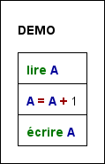
Plain diagram versus highlighted diagram (in standard and C operator mode)
You will find plenty of examples throughout this User Guide and, of course, in practical use — it's quite straightforward.
Since version 3.30-14, syntax highlighting also applies to the popup showing the element text in display mode "Switch text/comments":

Remark: Before version 3.29-06, highlighting was the major cause of drawing contention, particularly in Arranger. Since version 3.29-09, these performance problems have been eliminated. Only the first drawing of a large amount of diagrams imported by code or loaded from an arrangement file may take a few seconds, therafter the time difference to drawing without highlighting is hardly perceptible anymore.
8.7. Operators in C style?
Since version 3.30-11 there is a new display mode for diagrams presenting all operators in C-style syntax, provided syntax highlighting is active. The mode can be switched on via the "View" menu (before version 3.32-13 the "Diagram" menu):

If enabled then the following conversions will be done on displaying the diagrams (unmodified operators not listed):
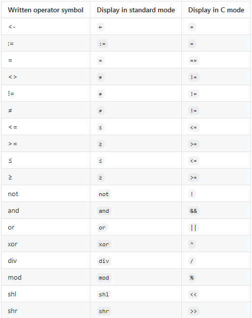
Please note that this mode does not alter the supported syntax for Structorizer elements, i.e. you will still have to enter the character combinations shown in the operator table of the Syntax section, e.g. to achieve a functional assignment in a diagram you need to write <- or :=. To use a simple equality sign (=) to assign values as in C and similar languages will not work. The mode only changes the apparition.
In order to reduce confusion, a display mode indicator was integrated in the toolbar (a tooltip explains the mode when the cursor is hovering over the indicator icon):
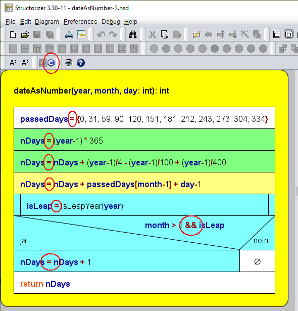
If the C-style operator display mode is off then the icon is grayed out (the tooltip of the disabled icon will still name the menu path where you may switch the mode on):
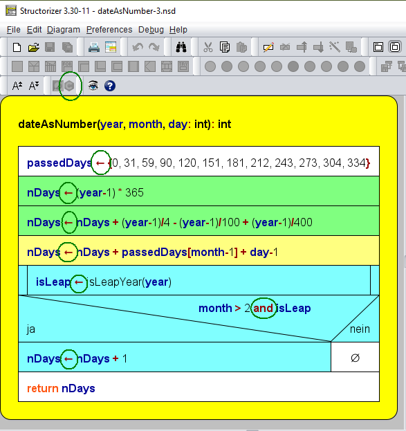
Since version 3.30-14, the operator conversion also applies to the popups showing the syntax-highlighted element text in display mode Switch text/comments.
8.8. DIN?
In DIN 66261, the German Institute for Standardization defined the appearance of Nassi-Shneiderman diagrams. Menu option "DIN?" (or "DIN 66261?") is to turn on a DIN-conform diagram representation.
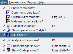
Actually, this setting affects only the FOR loop, because it is the sole element type, for which the Structorizer representation may differ from the DIN-66261 specification:
|
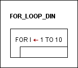
|
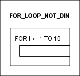
|
FOR loop in accordance with DIN 66261
("DIN?" checked; default in Structorizer since release 3.30) |
FOR loop not in accordance with DIN 66261
("DIN?" unchecked; default in Structorizer before release 3.30) |
Also note the appearance of different toolbar and menu icons depending on the setting.

Icon "FOR loop" with "DIN?" checked

Icon "FOR loop" with "DIN?" not checked
Note: You can alter freely between DIN and non-DIN mode. The appearance of all diagrams will immediately switch to the new mode. This is no modification of the diagrams themselves but only of their representation.
8.9. Analyse structogram?
In menu "View" (before version 3.32-13 in menu "Diagram") or by pressing key <F3> you may disable or enable the Analyser feature, which performs a "live" static analysis of your diagram with respect to syntactical, structural or certain semantic issues:
If Analyser is switched on, then the report list beneath the diagram work area becomes visible and presents the element-related check reports of Analyser, e.g.:

The checks are done very quickly but not in zero time, of course. So if you are not interested in syntactical and semantic checks but want to accelerate Structorizer, you may switch Analyser off. When switched off, then the report list will vanish.
In the Analyser Preferences you may opt in or out specific rules of the analysis. See Analyser Preferences for a list and a short explanation of the rules.
8.10. Show Arranger index?
The visibility of the scrollable Arranger index may be switched off or on via the menu item "View › Show Arranger index?" (before version 3.32-13 via menu item "Diagram › Show Arranger index?"):
If enabled then the index tree of all currently arranged diagrams by groups will appear aside the work area unless the Arranger doesn't contain any diagrams or the Structorizer instance isn't associated (i.e. doesn't listen) to the Arranger:
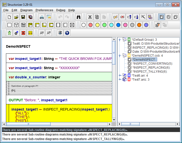
See the Arranger index section on the Arranger manual page for details how to work with the Arranger index.
Note that the tabbed info pane will vanish when both Arranger index and Code preview are disabled.
8.11. Show code preview?
The visibility of the scrollable Code preview may be switched off or on via the menu item "View › Show Code preview?" (before version 3.32-13 menu item "Diagram › Show Arranger index?"):

If enabled then the code preview for the current diagram will appear aside the work area in the tabbed pane:
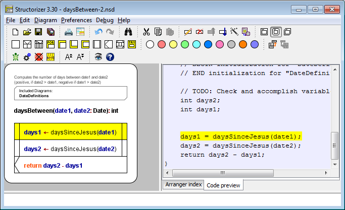
See section Code preview on the Code generator manual page for details how to control the code preview.
Note:
- The tabbed info pane will vanish when both Arranger index and Code preview are disabled.
- Neither this menu item nor the Code preview will be available if Structorizer was started in an I/O-restricted mode, which can be achieved via a central predominant ini file that contains a line "noExportImport=1" (versions ≥ 3.30-11).
9. Preferences
File-based customization
Structorizer may be customized in several ways: You may modify the text font, the set of selectible element colours, the dialogue language, the default contents for the elements, redundant (or decisive) keywords for different elements, code export options, and the look and feel. See the subsections for details.
By default, preferences are user-speciifically held in a configuration file (structorizer.ini) in your profile (see bottom of this section).
Usually the settings of the Preferences menu are automatically saved when you leave (close) Structorizer. Modfifications to some preferences, however, may immediately trigger the saving of all preferences, e.g. whenever you commit changes in the export option dialog.
You may force immediate saving by menu item "Preferences › Save or load preferences › Save now":
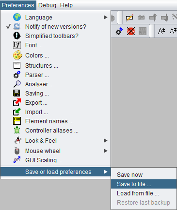
Preferences export and import
In certain contexts it may be desirable to change entire configuration sets frequently or to distribute a set (or subset) of preferences to other users. To facilitate this, the following menu item allows you to save the current configuration (or, since version 3.29-12, also parts of it) to an ini file with name and location of your choice:
Preferences › Save or load preferences › Save to file...
Before you are asked for the target file path, a selection dialog will open, offering the opportunitiy to restrict the export to some preference categories (subsets):
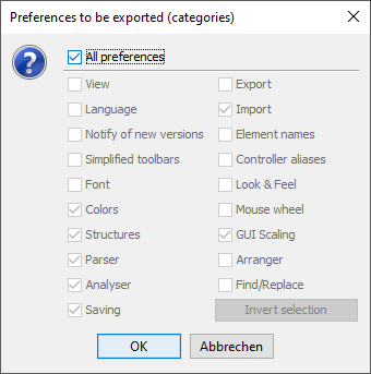
Initially, the checkbox "All preferences" will be selected, such that the category checkboxes below the separator line are inactive and would be ignored for the export. In order to store a subset of preferences you must unselect the checkbox "All preferences" and may then choose the categories you want to save.
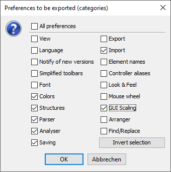
The button "Invert selection" will toggle the selection state of all categories in order to facilitate both positive (some categories) or negative selections (all but some categories). Structorizer will cache the last used category selection pattern for repeated preference exports with same subset but possibly modified option values (this cached category subset won't be stored for further sessions, though).
Note: An export with all offered categories selected will not be exactly the same as with "All preferences" active: Some options (like author name or name of the license file among the "Saving" options or the recent file history) don't make sense to be exported or don't belong to any of the categories, a complete set of all preferences will only be saved if "All preferences" is selected.
(Most categories simply correspond to the menu items of the "Preferences" menu. Category "View", however, refers to the presentation settings held in the "View" menu (before version 3.32-13: lower part of the "Diagram" menu). "Arranger" comprises some Arranger-specific options like the zoom factor, "Find/Replace" conveyes e.g. the search mode settings and the list of recent search and replace patterns from the Find & Replace tool.)
Selective export of preferences can be particularly helpful if you want to set up a central start preferences file in the installation folder.
In order to restore saved settings from an individually saved ini file, use menu item
Preferences › Save or load preferences › Load from file...
On loading preferences from an ini file, the previous preferences will automatically be backed up, such that you may restore them (via submenu item "Restore last backup", which will be enabled after loading a preference file) if the loaded preferences turn out to be unsuited. The backup will only be available within the current session, and it will be overwritten on any subsequent loading of preferences such that only the most recent setting can be restored.
Compensating unwanted impacts
If you decide to import preferences from some ini file then it will usually also comprise parser preferences, and these might of course differ from your recent settings. If some diagrams are being open (and relying on the current parser preferences) then they are likely to get stale. To avoid this, Structorizer identifies parser preference changes, shows you the replacement list, and offers you to refactor your diagrams i.e. to adapt them to the new set of parser strings. This might look like in the screenshot below:
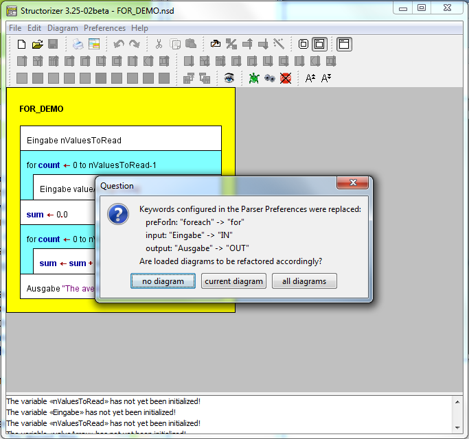
The image shows the Analyser warnings in the report area of Structorizer, which are due to the lost correspondence between used and loaded keywords, and it shows the question box listing all parser preference changes. Obviously, you may select among the refactoring of:
- no diagram,
- just the currently edited diagram, and
- all open diagrams (i.e. including those parked in an associated Arranger, not of course all diagrams stored in your file system).
(The dialog will not pop up if the current diagram is empty and no other diagrams are in the Arranger pool or if no parser preference changes were detected.)
Having pressed one of the buttons "current diagram" or "all diagrams", the resulting diagram(s) would become fully functional again, e.g.:
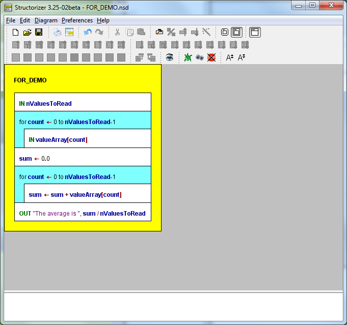
If you refactored diagrams by mistake or you happen not to be pleased with the outcome then you may simply press the "Undo" button to restore the original text. If you had opted to refactor all diagrams then the refactoring of every single diagram may be undone (and redone) independently. Just fetch the respective diagram from the Arranger into the Structorizer work area and press the "Undo" button or <Ctrl><Z>.
Standard location of the configuration file
In case of bugs or trouble it may be useful to know where the configuration file resides. As mentioned above, this will usually be some subfolder of the home directory associated with your local account. By default, the name of this subfolder will be ".structorizer" (such that it is hidden from a normal ls command in Linux), but under certain circumstances it may be a platform-dependent application data folder, e.g. "Library/Application/Structorizer" under Mac OS X.
Just consult the "Paths" tab in the "About" dialog, which is accessible via the "Help" menu or with key combination <Shift><F1>:

Command-line-specified preferences file (versions ≥ 3.29-13)
It is possible to specify an alternative ini file via commandline option on start, e.g. (where the underlined name is just a placeholder for the respective shell or batch script name or the path of the structorizer.exe file from the Windows installation directory):
Structorizer -s /usr/home/goofy/test/quirky.ini
Likewise, you might specify it in a Windows Desktop shortcut link as well:
But beware! If you specify a writable ini file in a command script or shortcut, which is available to many (or even all) users, then all of them will share this very ini file and concurrently write to it, which is bound to cause trouble, inconsistencies, and frustration! If you specify a publicly accessible readonly (i.e. write-protected) ini file, in contrast, then the preferences will initially be read from there, but every user's preference changes will be cached in an automatically created idividiual temporary ini file throughout the session. On next start, all individual changes will be gone (as the temporary ini file will have been forgotten), again the readonly ini file as specified in the command line will define all initial settings, a new temporary ini file will be created and so on. Of course, you might look for the actual path and name of the temporary ini file during the session (on the "Paths" tab of the "About" dialog) and copy it on time (or simply save the preferences to some permanent file within your protected reach before closing Structorizer) in order to load the preferences from this file as soon as Structorizer got started the next time.
So, when does it makes sense? Mostly, if you placed Structorizer on a mobile memory device (e.g. an USB stick) in order to work with it as guest on different computers, but want to keep your latest settings on the mobile memory. Then you may prepare the start script (or shortcut) of your mobile installation in this way (i.e. specifying a path on that very drive instead of using the guest home directory).
The specified path may contain system environment variables, of course, as it will be resolved by the operating system shell before starting Sructorizer. So something like %HOMEPATH%, %USERNAME%, %APPDATA% (for Windows) or $HOME, ${LOGNAME}, or $USER (for Linux) might be used to individualize the ini path (but why not use the standard location then?). Note that missing subdirectories along the specified path may automatically be created with this option, even if the creation of the ini file itself should fail! To establish the directory path may fail due to missing privileges. If the ini file redirection fails, however, then Structorizer will fall back to the user-sensitive standard ini file location.
If you want to impose some predominant start preferences for all users but allow them to keep all non-prescribed settings indiviually then the following mechanism is clearly preferrable. Moreover, it works on top of this!
Central predominant start preferences (versions ≥ 3.29-12)
You may place an adequately prepared "structorizer.ini" file (this name is mandatory in this case!) in the Structorizer installation directory (if you are in doubt then the "Paths" tab of the "About" dialog will reveal it); in a manual "installation" the ini file might alternatively be placed in the "Structorizer.app" folder. All preferences stored in this central ini file (it may contain a rather small subset of the available settings, see below) will override the respective individual settings held in the user's home directory (or an ini file specified in the command line, see above) every time the user starts a Structorizer session. None of the other individual settings will be touched. During the session, users may modify all preferences as they like, the preset ones inclusive. But as soon as they start Structorizer next time, the subset of preferences in the central ini file will again override the respective individual settings. This way, certain class-room start settings may be configured and be put to the installation directory in order to ensure some general standards (which can temporarily be changed by the students, though). Renaming or removing the central "structorizer.ini" file will avert the mechanism. Note that individual settings of the users will never be saved back to the central ini file (not even if it is writable) but always to the individual ini file (in the user's home directory). (In former versions, the presence of such a central ini file had the problematic effect that all users concurrently — and that means in a conflicting way! — wrote their settings, including the list of recent files and directories etc. to the common ini file, as it is the case with a command-line-specified ini file, see previous subsection.) So, all individual settings not being in conflict to the predominant central file will survive between sessions. It makes sense to limit the central predominant preferences to the necessary minimum. Note that this mechanism also overlays the one described in the previous subsection (i.e. it is still predominant over the command-line-specified ini file).
This mechanism is particularly helpful on PCs (e.g. in a computer pool) where a group of users logs in via the same local account (e.g. a common guest accont), in which case it might be cumbersome each time to get rid of some wanton or awkward preferences left by the preceding user. If you opt for such a central ini file, you may find it helpful that version 3.29-12 enabled Structorizer to export partial ini files, i.e. files with certain subsets of preference categories. See Preferences export and import above. This spares you an ardous manual modification of a full configuration file (which contains the numerous key-value pairs in random order).
A specific preference that only makes sense in a predominant ini file and may only manually be inserted is "noExportImport=1", as introduced by version 3.30-11. It suppresses all code export and code import features, i.e., removes them from all the menus and disables them. This mode cannot be switched off inidviually within the user's session. (It was introduced on customer request, for examination purposes.)
Note that the central predominant ini file may not prescribe the GUI Scaling factor ("scaleFactor") since this would prevent the user from effectively adapting the symbol sizes to her needs, because the impact of this preference is postponed to the next Structorizer start when it would already have been overridden again.
An obvious alternative way (and the only sensible way in versions before 3.29-12) to distribute certain settings is simply to export a template ini file from an appropriately configured Structorizer instance and to request all users to load this ini file into Structorizer via the "Preferences" menu at the beginning. In this case all subsequent individual modifications will last between sessions (unless the user loads the recommended ini file again).
9.1. Language
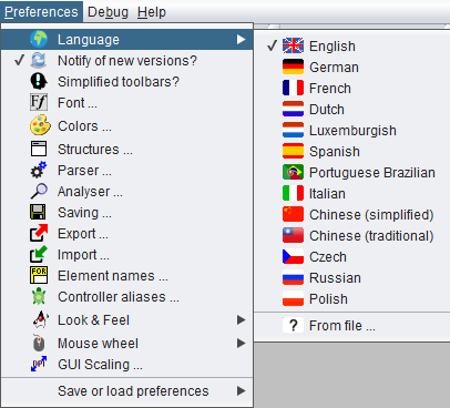
This preference (the menu item went to top with version 3.29-03, it had been "buried" near the end of the menu before) is responsible for the language of the graphical user interface. This preference is saved automatically. The menu item of the currently selected language is marked in a way depending on the selected Look and Feel, e.g. as a selected checkbox.
The set of translations and adaptations (e.g. menu mnemonics) associated to a certain language is called a locale.
The separated menu item " From file ..." (see image) allows you to load a locale file from your file system instead of one of the predefined translation sets provided by the menu. Such a locale file is a text file containing translations to an arbitrary language. It must of course adhere to a certain format and can be created or derived from an existing locale by means of a maintenance tool being part of Structorizer since release 3.25, called Translator (to be found in the File menu). This way, you are enabled (and invited!) to accomplish existing locales or to create new language files usable here. In Translator, you can advise a preview of the currently edited locale. While the preview is active, you will see a selected additional menu item in the preferences submenu:

You can end the Translator preview by selecting another menu item here (this will remove the extra item; the preview can only be reactivated from Translator).
Please notice that the language of the graphical user interface is independent of the syntax you use in your diagrams and vice versa! Some may prefer having an English user interface but all diagrams they draw need to be in French. Others might want to work with the GUI in their mother tongue while the diagram contents are written in English.
Hint: Several locales (language files) aren't quite complete (i.e. they haven't kept track with the many product enhancements of he last couple of years). The captions and messages for the most essential features are translated, however, GUI controls and messages with missing translations will usually be presented in English (which is the default locale). Sometimes, though, particularly after having changed the language, they may stick with the language previously used. In order to see at least English translations, switch to English and then back to your favourite language.
Since version 3.29-03, a welcome dialog will come up when you use Structorizer the first time; it offers the initial language choice — so you can't miss it:

When you select a language button then Structorizer will immedialtely change the menu captions etc. and also the language of the welcome pane:

If the chosen locale is not complete then the welcome text may still be in English but you will usually see an invitation to help accomplish the locale, advising to use the built-in Translator:

If you are a native or experienced speaker of a language, for which some translations are missing, defective, or wrong in Structorizer, then please don't hesitate to report the defective captions (e.g. as bug reports), to propose proper translations, or (even better still) feel invited to contribute to the accomplishment by producing an updated language file using the Translator and sending that file in.
9.2. Update search
Since version 3.25-09, Structorizer offers an automatic notification, if a newer version of Structorizer is available for download. For this purpose, Structorizer would retrieve the version number of the "latest version" from the Structorizer homepage whenever you start it. Structorizer will not of course send any personal data (except your IP address in order to obtain the response).
You will not be tracked. We think, however, that applications should not inadvertently connect to some internet site without being explicitly enabled to by their user. So it has always been an "opt in" feature, which is disabled by default.
Note: This preference is meant for manual installations of Structorizer (see Installation). If you work with the Windows installer distribution of Structorizer (or the Java WebStart distribution while it had still been supported) you will not need this mode, because in these cases the launcher will already be equipped with an update control mechanism that cares to get the newest package from the Structorizer homepage on every start of Structorizer.
This is where you may enable or disable this preference:
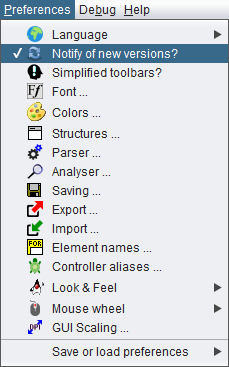
By activating the checkbox item "Notify of new versions" you allow Structorizer to request the version number of the most up-to-date Structorizer release downloadable as "latest version" from the Structorizer home page .
If the retrieved version number is newer than the one of your currently running Structorizer then a message box informing you on this newer version and where to obtain it from will pop up after Structorizer start:
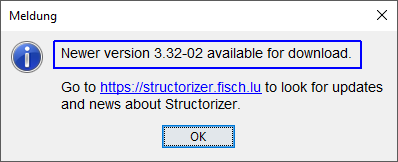
Actually, this is the same dialog being opened from menu item "Help › Update ... ".
Likewise, on opening the dialog associated to menu item "Help › About..." a hint will be shown in case a newer version is available if the preference "Notify of newer version" is active:
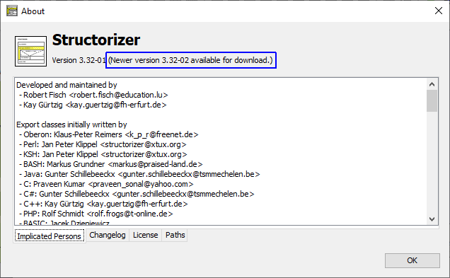
If you deselect the preference "Notify of new versions" then no connection to the Structorizer homepage will be tried and, consequently, no information about newer versions will be shown. On the other hand, a hint that this option is available will pop up on Structorizer start (it will be suppressed on using Java WebStart or the Windows installer as it doesn't make sense then):
Lest this information popup should annoy you every time you start Structorizer, while you do not want to deactivate the update notification, you may suppress this popup for all subsequent Structorizer starts of the same version, simply by pressing button "Don't show this window again". As mentioned, this popup suppression will only last till a new Structorizer version is installed. (Of course you may decide to enable or disable the update notification preference independently whenever you want.)
9.3. Simplified toolbars
Since version 3.27-02, there is an opportunity to reduce the abundance of the toolbars and menus and to work with a simplified subset of speed buttons and menu items, which may help the beginner to focus on the essentials whithout being confused by too many options:

This mode can be selected or ended over the menu item Preferences ›  Simplified toolbars?:

When you use the Structorizer the first time then a welcome message will offer you to start with this reduced mode and simultaneously to activate some little guide tours through the first steps of creating an algorithm in Structorizer:

If you opt for "Yes, reduced mode" then watch out for the messages in the bottom text pane of the Structorizer window (the "Analyser Report Area") — the guiding instructions will occur there, as the hint box, which will pop up when you activate guided tours, suggests:
9.4. Font
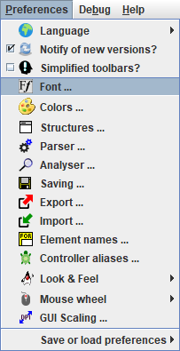
On the dialog shown in the following screenshot you can change the font that is used to draw your diagrams.
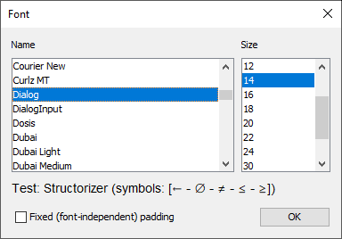
You need to choose a font that supports Unicode. Check the test string in the font dialog and make sure you see an arrow (←), the symbol for an empty set (∅), and the compound comparison operator symbols (≠, ≤, ≥) between the brackets.
The following fonts should be fine (as far as available):
- Cambria
- Dialog
- DialogInput
- Monospaced
- MS Gothic
- MS PGothic
- MS UI Gothic
- OpenSymbol
- SansSerif
- Segoe UI Symbol
- Serif
- Yu Gothic
If you just want to size up or down the current font then you might use the toolbar speedbuttons  or key combinations <Ctrl><Numpad+> / <Ctrl><Numpad-> instead. Since version 3.28-01 you may alternatively use the mouse wheel with <Ctrl> key pressed (zoom function).
Note: The font chosen here is only used for drawing the diagrams. It is not subject to the GUI Scaling preference. Both are completely independent.
Before version 3.28-08, the element padding (the margin around the text) had been constant, i.e. independent of the font size. This way, with a larger font, the text used to occupy a relatively greater share of the enclosing element than with a small font:
The same diagram in different font sizes with fixed padding
| Large font |
Small font |
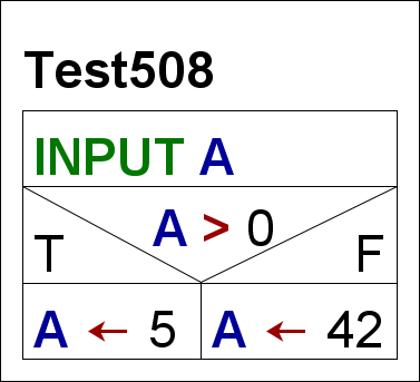 |
 |
Now (i.e. since version 3.28-08) the padding is by default relative to the font size such that the proportions of the diagram will no longer degrade on changing the font size. For backward compatibility, however, a checkbox was added to the font dialog allowing to force the traditional fix padding again:
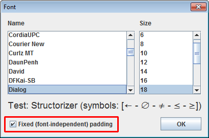
At the same occasion the line spacing was somewhat reduced, which particularly affects multi-line instruction elements.
9.5. Colors
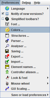
You can dye the elements of your diagram (and since version 3.32-28 also branch heads within forking elements) in arbitrary colours. The toolbar contains 10 buttons with different (default) colours:

(The 11th button showing a red Andrew's cross, as introduced with version 3.32-28, just allows to clear colours applied to branch selector areas within forking elements and is not customizable.)
These colours may be customized via the colour preference dialog.
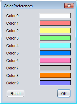
In order to modify a colour, you simply need to click on the respective rectangle and select a new colour in the OS-specific colour choose dialog that will pop up:
So you may "mix" your own palette very freely, without risk.
Note:
- Colours are saved individually with each element. This means that changing your default colours will not affect the colours of already dyed elements of existing diagrams. They will keep their original colour until someone explicitly changes it.
- If the colours in the menu happen to be totally diverged you may restore the original standard colour set by simply pressing the "Reset" button in the "Color Preferences" dialog (versions ≥ 3.28-13):
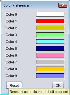
- You may save (and restore) individual 10-tuples of favourite colours without affecting other settings via a selective preference export.
9.6. Structures
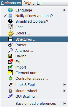
In this dialog, you can define the default content of newly created elements and some layout options.
Default Texts
Whenever you add a new element to your diagram, the element editor will pop up. As far as it is a structured element of one of the types IF statement (Alternative), CASE statement (Selection), FOR loop, WHILE loop, or REPEAT loop, the text area will already be filled with the respective content configured among the Structure Preferences. Since version 3.32-15, the caret will automatically be placed at the first question mark in the default text. Hence, question marks in the default text are good markers for the place to fill in the effective content. For "atomic" element types (like Instructions, CALL, and EXIT elements) as well as ENDLESS loops, PARALLEL sections, and TRY elements there is no such default text configuration (see Layout Options below).
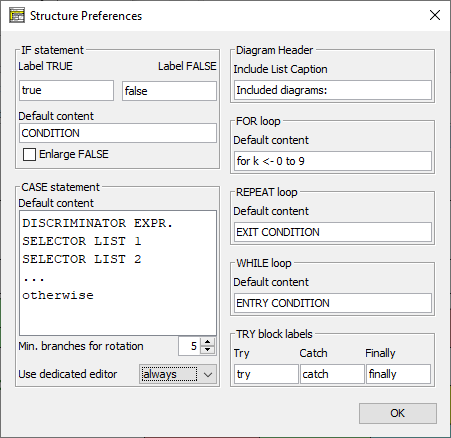
For the beginner, the default content could verbosely express the semantics of what it is to be replaced with (image above), for the expert, in contrast, very short symbols being easier to be overwritten may be preferrable (image below), though the automatic caret positioning at the (first) question mark in the element editor as introduced with version 3.32-15 compensates the drawback of verbous default texts.
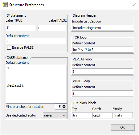
The default texts may also contain key phrases defined in the Parser Preferences for the respective element type as shown in the following image (with french words assumed in the Parser Preferences). These phrases may remain in the element (making it better readable perhaps) because they will be stripped off automatically on execution and code export. In the default text for the FOR loop, however, the keywords defined in the Parser Preferences play a decisive role on classifying the loop style and identifying its parameters, at least if you use the default text as template for the actual loop headline (see the FOR loop section of this User Guide for details).
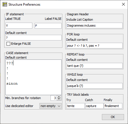
Caring for consistency, Structorizer offers to adapt the default texts in the Structure Preferences on changing the Parser Preferences:
Notice: Except for the connections described above, the preferences defined here have little to do with the Parser Preferences.
Layout Options
The Label TRUE and Label FALSE texts are just used to label the branches of IF statements in the diagram. In theory, you might specify arbitrary texts here but it's wise to use short words or even single characters since the lengths of these texts have an impact on the width of the IF elements, such that longer designations are likely to inflate the entire diagram. The labels are not stored with the elements — to change these labels here means to alter the representation of all diagrams containing IF elements (alternatives) at once.
The option Enlarge False specifies to which of the two branches of an alternative possible horizontal extra space is to be put. Extra space occurs if there is a very wide element above or below the IF statement, this way forcing the latter to be widened beyond its needed space as well. By default the extra space will widen the TRUE (left-hand) branch — this can be seen in the diagram at page end, just above the CASE element —, if you select Enlarge FALSE, however, then the right-hand branch will be widened instead. The extra space will not be distributed equally among the two branches!
Min. branches for rotation is an option for CASE elements with a large number of branches. CASE selections with numerous branches may result in diagrams that are much wider than your screen, such that navigation and overview get compromised. Often the contents of the majority of the branches of such broad-spread selections are single instructions (typically there are either numerous or large cases, rarely both at once). For this situation, the option offers to rotate all branches consisting of a single atomic or collapsed element as soon as the specified number of branches is exceeded, such that they consume much less width. Value 0 means to switch off this option, value 1 practically always tries to rotate. If some branches consist of large compound elements (e.g. loops, alternatives, or CASE selections as well) then they won't be rotated unless they are collapsed. Complex branches could also be "outsourced" to subroutines, this way being substituted by the respective CALL element, which counts as atomic and can hence be rotated:
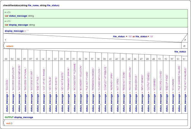
The Include List Caption is a label used as headline of the includes list region for diagrams referring to Includable diagrams (see red frame):
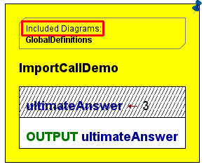
The TRY block labels (since version 3.29-07) are used to decorate the TRY elements in the diagram representation:
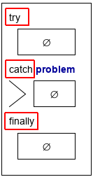
Editor choice
With version 3.30-15, a new kind of preference was introduced (and extended with version 3.32-28): In the CASE element area, you may decide whether you are fine with the standard element editor on editing CASE elements or if you prefer the specialized editor variant for CASE elements (you may even restrict this to CASE elements with non-empty branches):
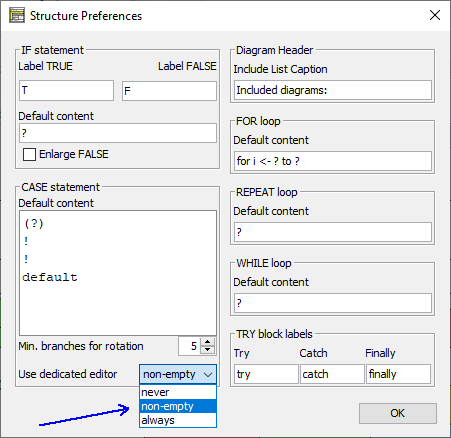
Among the major advantages of the special editor (which offers to set the discriminator expression and the default branch label in separate text fields and the selector lists for the branches in a table view) over the standard element editor are:
- the option to maintain the bond between existing branches (element sequences) and the commanding selector lists (and possibly colours applied to branch selector areas) on reordering the case lines,
- specific assistence for enumerator types,
- several consistency checking mechanisms.
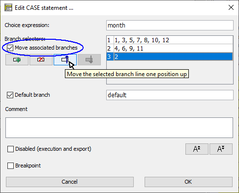
The option "non-empty" may be a happy medium between "never" (allows quick editing but offers no consistency assistance) and "always" (which may seem unnecessarily tedious, particularly on new CASE elements. With "non-empty" chosen, the specialised editor will not be used for new CASE elements, such that you may quickly enter the sepecifiation as multi-line text, and existing CASE elements without substantal branches such that no harm can be done by rearranging lines. On the other hand, for the modification of established CASE elements where a dissociation between selector lines and branches could result in a real mess, the specialised will be invoked.
9.7. Parser
Generally, structograms are meant to be free of a specific syntax, but if you want to benefit from the advanced features of Structorizer (e.g. test execution, code export, code import etc.), you must allow Structorizer to classify or identify certain details of the algorithmic structures. Therefore it needs certain keywords in the element texts. For instance, the correct detection and semantical distinction of FOR loops depends on such keywords. This also holds for the identification of input and output instructions and EXIT elements, and for the correct extraction of conditions in loop headers generally.
But you are free to specify (customize) these keywords according to your own preferences and needs. This is what the Parser Preferences are for.
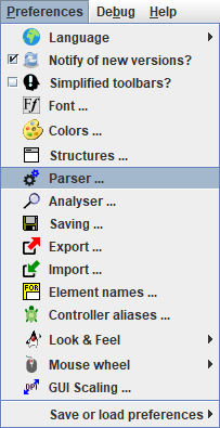
Via the menu path "Preferences › Parser..." you may open the Parser Preferences form. From version 3.29-04 on, it shows you by a different field background colour which of the keywords are neglectible and which are mandatory for correct element analysis:
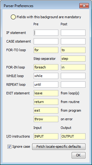
For most control structures, you can define a leading "Pre" and trailing "Post" keyword, where "Pre" and "Post" refers to the characteristical text content you are to enter in the element editor on inserting an element of that kind (e.g. the condition of an alternative or loop). So Structorizer will know what prefix and postfix can be ignored in order to extract the actual logical expression. Some control structures like FOR loops and EXIT statements, however, require more keywords to separate several expressions in the element text or to classify the denoted action of the element. Depending on what module uses the diagram parser (see below), these keywords are being filtered out, replaced, or used to split the text.
Since version 3.30-07, there is another possible impact of the "Pre" and "Post" keywords for IF and CASE statements as well as WHILE and REPEAT loops on code import: If the import preference "Place configured optional keywords around conditions" is active then the imported condition expression will be enclosed by the non-empty "Pre" and "Post" keywords in the text field of the derived element.
The checkbox "Ignore case" controls whether the parser keywords configured here are to be matched in a case-sensitive or case-ignorant (or say tolerant) way, the latter being the default, e.g. it wouldn't make a difference whether you write "INPUT", "input", or "Input" (or even "iNpUt") in your diagrams; Structorizer would recognise it while option "Ignore case" is active. Be aware, however, that this case tolerance only applies to the keywords configured here, not to variable names.
The most important features and modules that may consult the parser preferences are:
If you do not intend to use any of them or if you are fine with the pre-configured set of keywords, then you may abstain from adjusting the parser preferences.
In most cases, however, you may want input and output instructions detected, FOR loops properly interpreted etc. In this case you will either have to stick to the configured parser preferences on writing diagrams or to adapt the parser preferences to the keywords used in the diagram.
The parser preferences are completely independent from the current dialog language (cf "Preferences > Language"), but since version 3.29-05 you may load localized keyword sets for some of the available languages via the pop-up menu associated to button "Fetch locale-specific defaults":
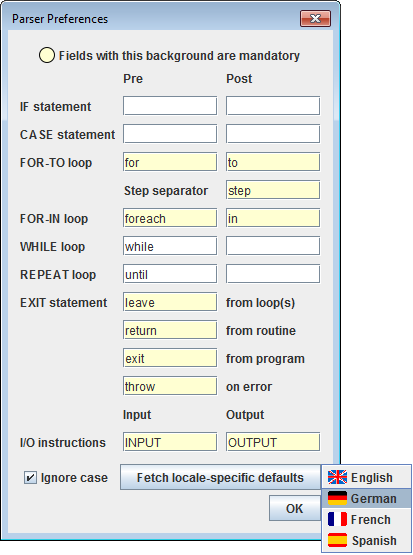
(The localized keyword sets are held in the resource locales, which are configurable by means of the Translator tool.)
After having selected the "French" menu item, the text field contenst could look like this:
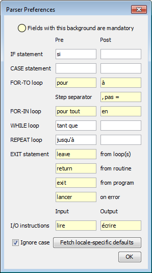
If you don't want to adopt the selected localized keyword set you may choose another one or simply quit the dialog without committing. (You do so by closing it via the respective control in the window heading or by pressing the <Esc> key.)
But now, what about a "working" diagram in Structorizer when you alter some of the parser keywords (and commit the changes)? Wouldn't it get "stale" and lose interpretability? Fortunately not! Structorizer will helpfully offer a handy service: Refactoring parser keywords in diagrams. If you commit changes to one or more of the keywords in this dialog, and the currently edited diagram isn't empty or there are diagrams parked in the Arranger, then you will be asked, whether:
- no diagram,
- the diagram currently edited, or
- all open diagrams (i. e. including those that are parked in an attached Arranger)
be automatically adapted to the new parser preferences — as far as they had matched the previous ones. This way, you can refactor an entire set of diagrams to use e.g. French keywords like "pour", "à", and ", pas = " in FOR loops instead of the English ones ("for", "to", "step") shown in the screenshot above:
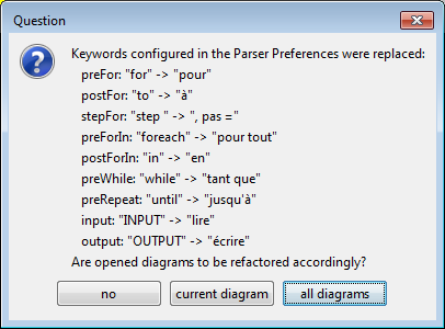
The translation of the diagrams induced by pressing the "OK" button is individually undoable for every affected diagram.
Obviously, for loading diagrams that have been created in a context with differing keywords, a similar problem might occur. And so it would when you load some archived preferences. But Structorizer is prepared: See Import options and loading preferences for the related aspects of diagram refactoring.
Note:
- Though Parser settings are technically independent of the "structures" preferences, it makes sense, of course, to configure e.g. the "Pre" condition keyword of a REPEAT loop as "until" if you happened to specify the default text for the Repeat loop as e.g. "until EXIT_CONDITION" or "until ?" in the "structures" preferences. With FOR and FOR-IN loops, in contrast, the default phrase in the "structures" preferences is split by the element editor based on the "Pre" and "Post" keywords configured here in order to decide the style and the parameters of the loop. Therefore you will typically be offered automatically to adapt the structure preferences consistently when you changed the Parser Preferences (but not the other way round).
- The "Pre" keyword of the FOR-IN loop is not required to differ from that of the FOR loop. In versions before 3.29-04 it was even allowed to be empty — in this case Structorizer assumed that the "Pre" keyword of the FOR loop served also as "Pre" keyword for the FOR-IN loop (though this behaviour was flawed in some aspects, so it won't be supported any longer). The "Post" keyword of the FOR-IN loop must not be equal to any other keyword of the parser preferences (this is to ensure that Structorizer is able to tell a FOR-IN loop from a FOR loop, in case both "Pre" keywords are equal).
- The keywords for the EXIT statement and for input and output instructions must mutually differ.
- None of the keywords must contain a colon (':').
- The keyword fields marked in cream colour in the screenshot above specify mandatory key words and must not be empty. Before version 3.29-04, Structorizer had not checked them but you would have to face some functional misbehaviour in Structorizer if you ignored this fact and emptied some of the mandatory fields. From version 3.29-04 on, you will be prevented from committing incomplete data:

- The localized keyword sets are configured in the locale resources of Structorizer. As already stated above, the Translator tool may be used to do so (but you must send in the resulting language file for product integration):
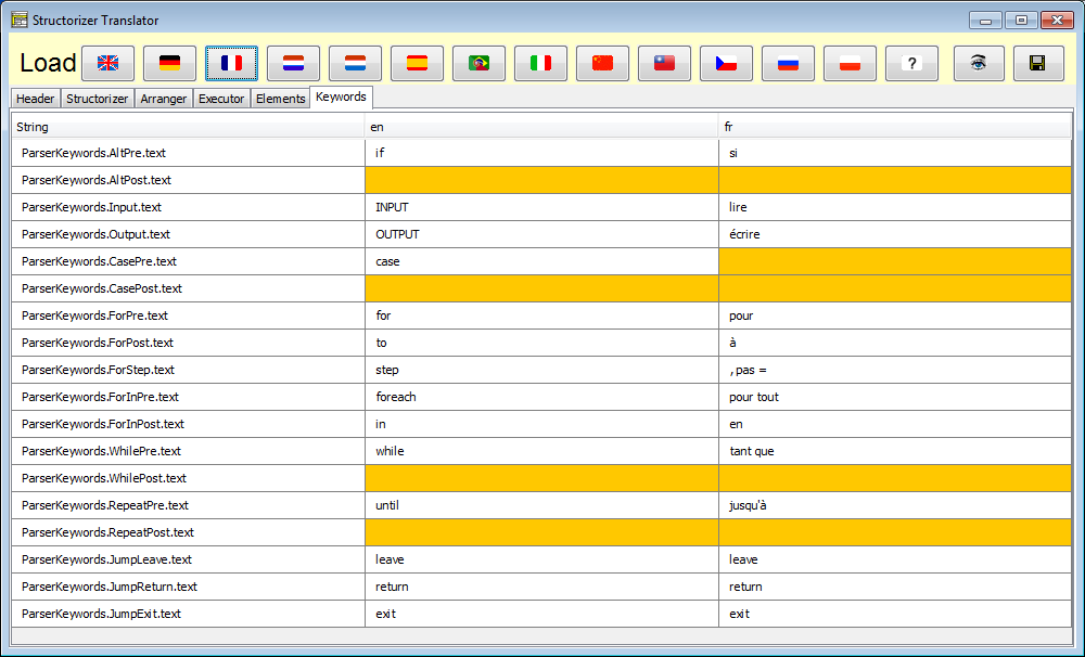
9.8. Analyser
The Analyser Preferences Dialog
The Analyser Preferences dialog is opened by means of the Preferences menu:
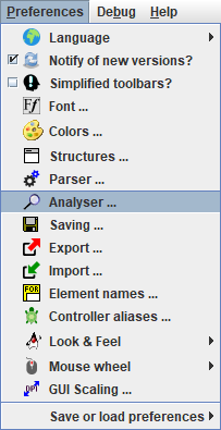
The Analyser is an advanced feature, which steadfastly analyses the structogram against different rules that structograms should comply with and checks it for obvious inconsistencies (like loops where the body has no impact on the condition and hence may unwillingly form an eternal loop).
The Analyser rules available for configuration are presented in a multi-tab dialog. It roughly categorizes the rules into
- essential algorithmic tests;
- general syntax checks (since version 3.32-01);
- checks concerning identifier naming and code style conventions; and
- hints and tutoring (see Guided Tours / Tutoring):
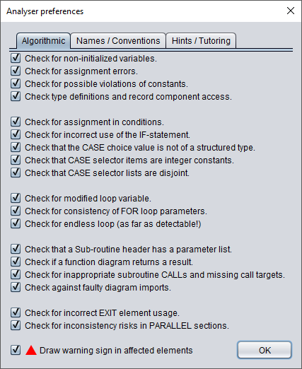
Since version 3.30-14, the elements related to one or more warnings in the Analyser report, will by default be marked with a small red triangle in the upper left corner (see example screenshots further below) in order to draw the user's attention to the warnings in the report list. The introduction of this feature was accompanied by the new checkbox at the bottom of the Analyser Preferences dialog, saying "Draw warning sign in affected elements" (see screenshot above). By unselecting this checkbox you may switch off this indication. (It will also be suppressed by disabling Analyser, of course.)
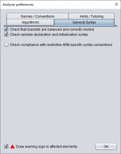
Among the convention rules there are also several ones that have been specially designed for Luxemburgish students. In Luxemburgish schools these rules are mandatory. The most special ones of this kind are marked with "(LUX/MEN)". So you may opt them out if you haven't to obey these rules.
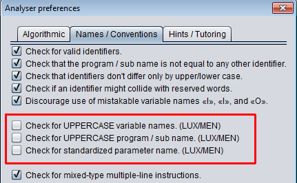
Actually, each rule can be enabled or disabled independently. The analyser itself can be activated or disabled as a whole via the "View" menu (see Settings > Analyse structogram?) or by pressing the <F3> key.
The analyser strongly relies on the Parser Preferences. If, syntactically seen, you don't stick very close to them, the analyser will not work correctly but probably produce a lot of needless warnings.
Note: As it is proven that a program can never absolutely predict the behaviour of another program, the messages produced by the analyser should at best be considered as hints. They might be misleading or even wrong in certain cases!
The fourth tab is dedicated to some smoothly guided tours. Two prototypes of them are available since version 3.27-02. Further ones are likely to be added:
Rule Type Explanation
(Checkbox order may change, this list follows the one presented by version 3.25-07, see screenshots above.)
Instructions
- Check for non-initialized variables.
See Analyser for examples. This check reports all names occurring in expressions and adhering to strict identifier syntax (see "Ceck for valid identifiers" below), which have not been initialized in a preceding instruction. This includes all names for which there is no initialisation at all. This means if a variable was used prior to its first assignment. Varisables initialized only in some branches of an alternative or CASE statement are also reported as potentially uninitialized.
- Check for assignment errors.
This analysis detects instruction lines containing an equality comparison operator but no assignment operator. Since in many languages (including C, Java, PHP, etc.) the single equality sign '=' is used as assignment operator, unfortunately, one easily writes it here as well, instead of := or <-, so the check will warn in such cases. The check doesn't make sense, therefore, if you willingly fill in source code complying with the syntax of such a programming language (see No conversion of the expression/instruction contents in Export Options, by the way) and aren't interested in language-independent executability.
- Check for possible violations of constants.
If enabled, Analyser will complain on any attempt to redefine or modify the value of a defined constant. Examples:
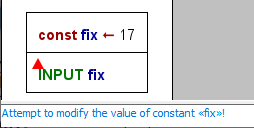
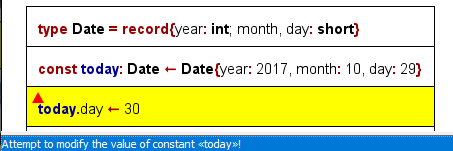
- Check type definitions.
This analysis checks e.g. whether type definitions are syntactically incorrect or duplicate or contradicting or if variables don't adhere to their defined structure or e.g. aren't declared but used as records (chiefly in case of record variables):
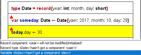
Conditions and Alternatives
- Check for assignment in conditions
Though legal in languages like C, a condition test shouldn't have side-effects in structured programming, in particular, there should not be an assignment operator in conditions of loops, alternatives or CASE statements. (Executor would handle it as an error, anyway.) The legality of assignments in C conditions is a common source for bugs (accidently an assignment operator = is used instead of the intended == comparison operator). Note that Executor does not allow to execute a call to another subroutine diagram in a condition (which would also raise the risk of a clandestine value change).
- Check for incorrect use of the IF-statement
If only one branch of an IF statement is needed then the "TRUE" branch (i.e. the left branch) is to be used. (This is quite easy to achieve by negating the condition if necessary, you might use the magic wand button  to flip an alternative.) Analyser reports IF statements where the "TRUE" branch is empty no matter if the "FALSE" branch contains instructions.
- Check that CASE choice value is not of a structured type (versions ≥ 3.30-16)
The detection of the applicable case in a CASE element relies on a comparison among discrete values of some primitive type, many programming languages even require them to be integral values or characters (enumerator types are perfect). Structured types (i.e. arrays or records/structs), however, do not make sense in nearly any case. This option will activate warnings if the choice expression doubtlessly represents a structured type.
- Check that CASE selector items are integer constants (versions ≥ 3.30-02)
Though Structorizer supports even variables and string literals as selector values for the branches of CASE elements, some target programming languages for code export (e.g. C, C++, C#, Java etc.) may not so, they may only accept integral constants (including character literals and enumerator type values). This analyser option will check that all selector items are integral constants.
- Check that CASE selector lists are disjoint (versions ≥ 3.30-02)
If a selector value occurs in several branch labels of a CASE element or even if it occurs more than once in the selector list for one branch then this check will produce an entry in the report list. Though Structorizer and many programming languages simply resolve branching conflicts by going to the first branch with a matching selector, Analyser will report selector values occurring more than once in the branch labels of a CASE element with this check enabled, as it usually signals a design mistake.
Loops
- Check for modified loop variable
The manipulation of the counter variable of a For loop by the loop body is regarded as a no-go (though often seen in C or Java code), some programming languages (like Pascal) do explicitly prohibit this interference with the loop control mechanism. Moreover, syntax errors like too few (i.e. none) or too many counter variables in the loop header are reported if this option is chosen.
- Check for consistency of FOR loop parameters
A For loop is a conveniently combined loop, which may adhere to one of two different types (counting loop / traversing loop). A dedicated editing support for the header is provided (see there), resulting in some possible redundancy between the specific entry fields and the full text. Whereas the element editor tries to synchronize the information according to the detected type, loading a diagram that had been created under different pereference settings may not fit into the consistency requirements. This Analyser check detects logical differences or even conflicts among the representations. In case of a counting loop it further generates a warning if step value is configured not beeing a legal no-zero integer constant. It also detects if a variable name collides with a configured FOR loop parser keyword.
- Check for endless loop (as far as detectable!)
Unlike intentionally inserted endless loops, an algorithm must be able to leave a loop eventually. While a FOR loop has a counting mechanism where the loop body should not interfere, an impact of the loop body on the loop condition of WHILE and REPEAT loops is necessary. Hence, if the loop body does not change the value of any of the variables refered to by the loop condition, the Analyser will assume that the algorithm probably fails to get out of the loop.
Functions/Procedures and Calls
- Check that a subroutine header has a parameter list
Subroutines (functions / procedures) do some subordinate work within a program. Some subroutines just execute a fixed algorithm without alteration, but usually subroutine calls apply an algorithm to different sets of appropriate data (e.g. in order to compute the medium value of some array of numbers) where these data (e.g. the respective array) are to be passed to the subroutine as parameters. The list of parameter names is expected to be enclosed by parentheses and immediately to follow the subroutine name. This check ensures that such a parenthesized parameter list is present. It may be empty (if the subroutine doesn't need arguments), but at least the parentheses should be there. A main program header, however, may come without parameter list. So this check only applies to subroutine diagrams. (Structorizer may tolerate a subroutine diagram with missing parameter list and handle it as if it had an empty parameter list, but programming languages might regard a missing parameter list as syntax error.)
- Check if, in case of a function, it returns a result
A diagram of subroutine type will often represent a function, i.e. a mapping of input data to result data, the latter of which are to be returned to the calling program level. If this check is enabled then it analyses whether or not the routine will provide such a result value in any case (i.e. no matter which path through the algorithm is taken). Be aware that Structorizer supports several ways to provide a result value:
- by using a return instruction,
- by assigning the value to a variable named "result" or "RESULT",
- by assigning the value to a variable named after the routine.
Therefore it is also checked if the function happens to employ more than one of these three mechanisms, which causes ambiguity.
- Check for inappropriate subroutine CALLs and missing call targets.
The content of a CALL element should either be a bare external procedure call or a simple assignment instruction with a bare external function call as expression (where "bare" means that there is no further expression around). The procedure or function name must be followed by an argument list, which is — similar to the parameter list in a subroutine header — to be enclosed between parentheses (but may be empty). The arguments may be complex expressions (but are supposed not to contain external procedure or function calls themselves). The analysis here checks whether some of these restrictions are violated. Neither Executor nor code export would accept a CALL that doesn't stick to the prescribed syntax.
If the syntax is verified then Analyser also checks whether the called subroutine is currently available.
Jumps and Parallel Sections
- Check for incorrect EXIT element usage
Any of the following issues are reported:
- EXIT elements, which are neither empty nor start with "leave", "return", "exit", or "throw" keyword (or what's configured for them in the Parser Preferences);
- Return instructions that are situated neither at diagram end nor in an EXIT element;
- Instructions starting with an "exit" or "leave" ("break") keyword outside of an EXIT element;
- leave/break instructions outside a loop or specifying more levels to leave than being nested in;
- return instructions in a branch of a PARALLEL section;
- exit or leave instructions with illegal parameters (only integer constants are allowed);
- Instructions directly following an EXIT element of arbitrary type (unreachable).
- Check for inconsistency risks in PARALLEL sections
If a variable being subject to modification in one of the threads of a PARALLEL section is also used in concurrent threads of the same PARALLEL section then this is reported as a potential hazard.
General Syntax
- Check that brackets are balanced and correctly nested (versions ≥ 3.32-01)
Induces a warning if the number of opening (i.e. left) parentheses, brackets, or braces does not match the number of closing (i.e. right) ones in expressions and instructions. Likewise the correct correspondence of left and right brackets of the appropriate type, regarding recursive nesting, is analysed and glitches are signalled.
- Check variable declaration and initialisation syntax (versions ≥ 3.32-13)
Checks that variable declarations in Pascal/Basic style introduce new identifiers, that the associated type specification is correct (either a known type name or an array construction over a named type), that only a single variable identifier is introduced with an initialisation, that a declaration in C/Java style is combined with an initialisation, e.g:
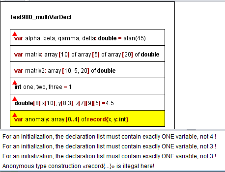
- Check compliance with ARM-specific syntax conventions (versions ≥ 3.32-05)
This option enforces a very draconic grammar check on all elements, which is related to the ARM code generator. Representing a RISC architecture, ARM processors provide a reduced but highly regular instruction set. Structorizer might be used to design algorithms in the spirit of this philosophy on a low level. To support such an approach, a grammar was defined that reflects as close as possible the ARM instruction capabilities (an exact equivalence is not achievable, though, cf. Special syntax for ARM). With this check option enabled, there will be warning on element content that is more complex than the machine level could directly interpret (more exactly: that is not complying with the imposed grammar rules). No matter whether ARM generator may actually provide e.g. a compilation of a hierarchic mathematical expression, the restricted check will only accept simple operations between two operands, of which the first one may be a variable or register name and the second one either a variable or register name or a literal. This may or may not be combined with a related ARM-generator-specific export option to reject non-elementary content.
Identifiers and Naming Conventions
- Check for valid identifiers
Induces a warning if a character sequence introduced as variable or routine name does not adhere to strict identifier syntax: only consisting of ASCII letters (of the English alphabet), digits, and underscores, not starting with a digit. See below for even more restrictive naming conventions.
- Check that the program / sub name is not equal to any other identifier.
Interestingly, in languages like Pascal a value assignment to a variable named after the subroutine itself is the official way to prepare the value return (and Structorizer supports this behaviour, too). If recursion is allowed (which should be in high-level languages), it must of course be possible to refer to the same name within a nested recursive function CALL. In other contexts, however, the occurrence of the program / subroutine name in some expressions may be a sign of a potential bug. That's where this option makes sense.
- Check that identifiers don't differ only by upper/lower case.
Many programming languages (like C, Java, Oberon etc.) dinstinguish upper-case and lower-case letters in identifiers of variables, procedures etc. So does the Executor. Other languages (like Pascal) don't. To use names like bad, Bad, BAD, bAd, baD etc. in the same diagram is therefore not only bad style but also a limiting factor for the range of export languages, because names meant to be synonyms might be distinguished or — the other way round — names thought of being distinct could be regarded as identical — both corrupting the algorithm. This check, being activated, will report every introduction of a new variable that only differs in letter case from others, previously assigned ones.
- Checks if an identifier might collide with reserved words.
Most programming languages use a set of reserved words — designating algorithm structures, data structures, or primitive data types. If you name a variable like one of these reserved words then the result of a code export to the respective language will cause trouble. Based on lists of important reserved words of all programming languages a code generator is plugged in for, this check will point out all instructions introducing a variable name with potential keyword collisions (and will list the languages known to use this name as reserved word).
- Discourage use of mistakable variable names «I», «l», and «O»
Letters "I" (upper-case i) and "l" (lower-case L) are very hard to distinguish in many fonts, moreover they may resemble the digit 1 in other fonts. The same holds for letter "O" (upper-case o), which is easily mistakable with the number 0. Is it already questionable to use single-letter identifiers at all (except within limited scope or for well-accepted concepts like coordinate names x or y), then the use of one-letter names "I", "l", and "O" as variable identifiers is a really bad idea (an absolute no-go, actually). With this check enabled, the analyser will express a respective warning wherever one of these three error-prone variable identifiers is introduced.
- Check for UPPERCASE variable names. (LUX/MEN)
In Luxembourg, the Ministry of Education prescribed that at public schools variable names be written in UPPERCASE. (Elsewhere this may not be a wanted code style demand.)
- Check for UPPERCASE program / sub name. (LUX/MEN)
In Luxembourg, the Ministry of Education prescribed that at public schools program and subroutine names be written in UPPERCASE. (Elsewhere this may not be a wanted code style demand.)
- Check for standardized parameter name. (LUX/MEN)
In Luxembourg, the Ministry of Education prescribed that at public schools parameter names be not only written in UPPERCASE have to be prefixed by a lower-case 'p' letter, such that "pSOMETHING" would be a legal parameter name whereas "SOMETHING" wouldn't. (Elsewhere this may not be a wanted code style demand.)
- Check for mixed-type multiple-line instructions.
Structorizer copes with Instruction elements that contain several lines. However, if you regard an Instruction element that contains both input and output statements or one of them together with assignments as violation of NSD principles, then this check will find such unwanted elements.
By the way, you may easily convert a multi-line Instruction element into a sequence of single-line Instruction elements by means of the Transmutation button  .
.
Guided Tours / Tutoring
Rather than introducing some dedicated assistants or dialogs, the guided tours just steer you smoothly via recommending hints in the Analyser report list. Ideally you start with an empty diagram (<Ctrl><N>). Then you will see some messages in the lower pane, one of them is a note informing you that a guide is switched on and how to switch it off. A little blue marker triangle will also remind you that there are tutorial hints in the report list (from version 3.30-14 on; among the tutorial hints there may be regular Analyser warnings, in which case the marker will be red):

- Short "Hello World" tour.
Guides through the creation and use of a "hello world" program.
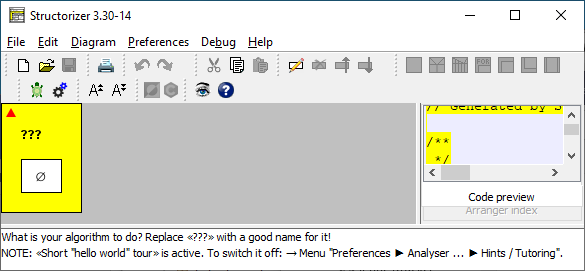
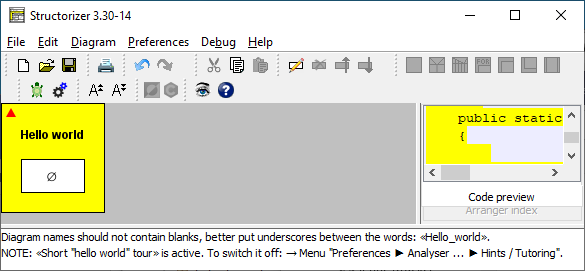
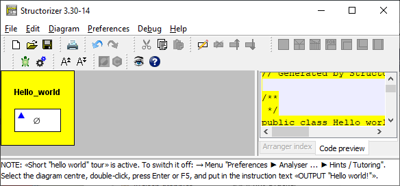


- Guide to first program instructions (IPO model).
Like the Short "Hello World" tour, the insertion of an input instruction, an output instruction, and a processing instruction between them is recommended, but it already offers more freedom of choice. (Btw. IPO means "Input — Processing — Output", a fundamental and traditional division of a program into the three phases of data acquision, data processing, and data output. Even with modern interactive applications, it makes sense to separate dialog and processing. Control processes, e.g. in automation and embedded systems, mostly also adhere to this model, often within an eternal loop: measurements / sensor monitoring, control decisions, control action.)
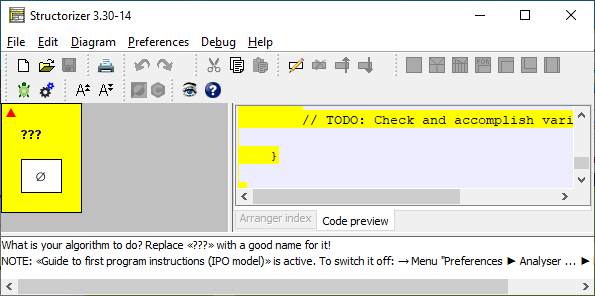
etc.
9.9. Saving options
Saving options have an impact on how and when diagram files are saved. These preferences are available for configuration via the Preferences menu:
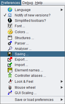
By selecting this menu item you will obtain the following dialog:
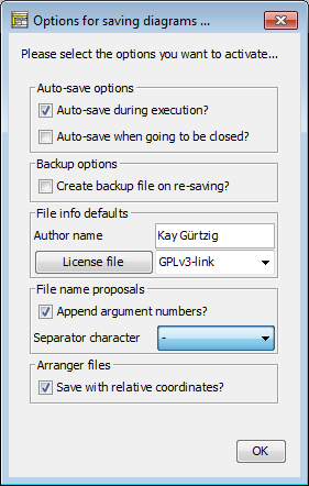
There are two options concerning auto-saving, another option related to file backups, and authorship / license options. Since version 3.29-07, there is an option concerning the file name proposals. Last but not least you can specify whether arrangements are saved with absolute or group-relative coordinates.
Auto-save options:
Usually, Structorizer will ask you interactively whether you want to store unsaved changes to a diagram as soon as you are going to replace it by another one in Structorizer, on going to close a dependent Structorizer instance holding a "dirty" diagram etc. Sometimes these questions are raised simply for safety reasons since the changes will not necessarily get lost even if you refuse saving them now. But then the changes stay pending and you are likely to get the same question later again. This situation is particularly annoying when a diagram (with unsaved changes) being executed is going to call a subroutine. Similarly on closing Arranger or some Structorizer instances.
If you would have saved these pending changes anyway then you may avoid the hassle by opting for up to two situations where pending changes of affected diagrams (and only these) shall automatically be saved without extra request for commit:
- during execution (as described above)
- on closing a dialog holding diagrams.
Note: To opt for "auto-save during execution" does
not mean that the diagram will automatically be saved on starting execution. Instead, auto-saving is only done when the execution arrives at a
CALL element, which induces the replacement of the current diagram by the called diagram in the work area.
Backup options:
The backup option addresses a behaviour that was introduced to avoid data losses in case an update of an existing NSD file failed. It could have happened that users ended up with an empty file. Therefore a twofold strategy was implemented: The old version of the file was renamed to <filename>.nsd.bak before the new version was saved. If you dislike the directory being polluted with these backup files, then you may now opt out the creation of backup files by unselecting the checkbox "Create backup files on re-saving?". Even for the rare case that the saving might fail this is safe enough now because actually the backup file will still be produced but only automatically removed after the saving has successfully ended.
File Info defaults:
These options specify, what author name is used for new diagrams and the "last modified by" diagram attribute on changes. The default is the system user name of your login.
In the same section, you may specify a license text to be added to every diagram you design and save. On the right-hand side there is a combobox allowing you to select the name of a license file residing in your "license pool" in folder ".structorizer" of your home directory. If there is none or if you want to create a new one from scratch or with a text from clipboard, you may enter a new license name. By pressing the button "License file" on the left-hand side you will open the Structorizer License Editor, which is a dedicated very simple text editor.
You may enter, paste or modify the text (or link) for the selected license name, then either save it under this name in your "license pool" (<Ctrl><S> or menu item "File › Save (to pool)") or save a copy under a different name in your pool (<Ctrl><Alt><S> or menu item "File › Save as ...").
Alternatively you may rename the existing license within the pool (<Ctrl><R> or menu item "File › Rename ...") or may delete the currently presented pool license (<Ctrl><D> or menu item "File › Delete").
Via the Edit menu or keys <Ctrl><Z> / <Ctrl><Y> you may undo or redo last changes, respectively. Via key <F5> or menu item "File › Reload/Revert" you may discard all changes since last saving of the license text.
File name proposals (versions ≥ 3.29-07):
When you save a diagram the first time, Structorizer will propose you a file that is derived from the diagram (program/routine) name and the number of arguments (in case of a subroutine diagram). By default, the argument number is appended to the routine name (separated by a hyphen i.e. a minus sign), e.g. lets assume your diagram header looks like this:
demo_routineA(a: int, b: string, c: double): bool
then the file name proposal will be: demo_routineA-3.nsd because the function has three arguments. The result type does not contribute to the proposed name. If a routine has optional parameters (a feature introduced with version 3.29-06) then both minimum and maximum argument number will be appended:
demo_routineB(a: int, b: string = "", c: double = 3.14): bool
leads by default to a file name proposal of demo_routineB-1-3, because the routine has at least 1 explicit argument and at most two of them.
This name extension was sensible because you may overload routine names, i.e. if you work with several diagrams of the same name they are distinguished by Structorizer while their argument numbers differ. If the file name proposal would only reflect the name then you might inadvertantly overwrite one routine diagram with another if you aren't quite alert, despite you will be warned bevore overwriting a file.
Though you may always alter the proposed file name before saving, it may be very cumbersome and annoying having to do so each time you save a diagram if the structure of the proposed file name does not please you. Now you may switch off the augmentation with argument numbers, or you can modify the separator character between name and argument numbers.The following characters may be selected as separator instead of the hyphen:
'_', '.', '!', '°', '#', '$', '&', '+', '=', '@', 'x'
Arranger files (versions ≥ 3.29-01):
Since version 3.29-01, a checkbox allows you to specify that arrangement lists or archives saved by Arranger may store relative diagram coordinates (i.e. coordinates referring to the bounding rectangle of the selected diagram set or group) rather than absolute coordinates. This is particuarly sensible if you save several subsets of a large arrangement in order to use them independently thereafter. With saved relative coordinates, the respective group will be loaded near the Arranger coordinate origin (upper left region), otherwise it will be placed at exactly the same coordinates they had when being saved. On the other hand, if you gathered several groups in the Arranger and you want to be able to restore this constellation later without amalgamating all diagrams into a single large group, then you may save all these groups separately but with absolute coordinates. So they will find their former place, thus preserving the original arrangement on loading all groups that had formed the original content of Arranger
9.10. Export options
From the "Preferences" menu you can open the "Export Options" dialog where general or target-language-specific preferences for the code export may be configured:

What do the options mean:
-
Character Set
You may control what character encoding to use on export. Usually one of ISO-8859-1 or UTF-8 would be most appropriate (at least in western or central Europe). While "List all?" isn't checked, the choice list will only offer you about six of the most common character sets. By enabling "List all?", in contrast, you will be offered several dozens of encodings, i.e. all your Java version will know of.
-
Favorite Code Export
If you often export code to a favourite programming language, then it may appear too cumbersome always to click through the menu "File › Export › Code › Java" (for example). There is a configurable short-hand for a preferred or frequently needed target language. It is present directly in the File menu and via accelerator key <Ctrl><Shift><X>:
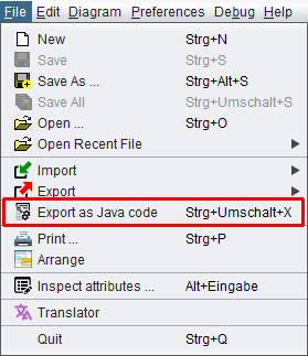
With export option Favorite Code Export you can select the target code for that menu entry and accelerator key.
Since version 3.29-03, there is a configurable count value next to the combobox for the favourite target language: It defines the number of consecutive successful exports to one and the same other target language after which a proposal to adopt this target langage as new favourite language is made:

If you confirm ("Yes" button) then this will have the same effect as if you had chosen the new Favorite Code Export here in the Export option dialog. As soon as you export once to a different language or switch the favourite language, the counting starts again from 1.
You may disable this proposal mechanism by decreasing the number in the spinner to 0 (also see the spinner tooltip).
Since release 3.30, you can also alter the favourite code export language simply via the context menu (popup menu) of the Code Preview.
-
No conversion of the expression/instruction contents (for all target languages)
Though Nassi-Shneiderman diagrams are basicly syntax-free and rather rely on structure, some Structorizer features like Executor and Analyser accept and work with a (somewhat eclectic) HLL syntax, aspects of which are described on the Syntax page. Consequently, code generators also derive the target code under the assumption that instructions and expressions are written in that executable and analysable Structorizer dialect.
This causes of course trouble if the text contents of the diagram elements have already been formulated according to the specific syntactical conventions of the intended target language. In this case, Structorizer would spoil the readily prepared text on export, trying to convert it again under false assumptions.
So if you work and document explicitly for one favourite language and used to fill in the element texts already adhering to the specific target language syntax then you may activate this checkbox, causing only the structural (and closely related) conversions but no (or only minimum) translation of the instruction lines, conditions etc. It is a kind of "raw export", particularly valuable for dedicated shell script development (because shell syntax is practically incompatible with HLL syntax conventions).
With version 3.32-32, the rules of this (hitherto somewhat vague) distinction were specified more explicitly and have been obeyed more strictly since.
-
-
Put block-opening brace on same line (relevant for C, C++, C#, and Java):
This option is related to the code style of compound instructions in C-like languages. If the option is activated then blocks will start (i.e. the position of the opening brace) at the end of the commanding line, e.g.
if (c == 0) {
a = 17;
}
Otherwise, the blocks will start at the beginning of the next line (indentation rules preserved, of course):
if (c == 0)
{
a = 17;
}
-
Involve called subroutines:
If this mode is active and your diagram to be exported contains CALL elements then the code generator looks for available matching diagrams (in the Arranger) and includes their code into the export. This way, if all required subroutine diagrams are found, the generated code will contain all necessary routine definitions to get the code runnning (after the usual manual post-processing). THe same applies for Includable diagrams referenced by the Include List of the exported diagram.
This option applies to all languages offered for export. The subroutine dependencies are analysed and a topological sorting is attempted, i.e. the code of a subroutine precedes that of its caller. Most compilers require this order. (Be aware, though, that the resulting code for e.g. BASIC with also switched-on line numbering may be dysfunctional because the numbered lines do not easily allow the insertion of larger bunches of code from a different place).
For group export (versions ≥ 3.30-07) the meaning is slightly different: If enabled then subroutines or Includables (see diagram type) from other groups may also be involved if referenced and not available within the same group. Otherwise their code will be missing in the exported file (you will get a warning that is listing the missing diagrams, though).
-
Export author and license attributes
If this mode is active (the default) then metainfo introduced with version 3.26-06 (name of the creator and last modifier of the diagram as well as the corresponding dates, license name and text as configurable with the Saving preferences) are also written as comments into the exported code. Otherwise they will not.
-
Propose export directory from NSD location if available (since version 3.30-07)
If this option is chosen (the default) and the diagram to be exported is associated to an .nsd file (because having been saved to or loaded from) then the file chooser dialog for the export will offer the directory of the nsd file as target folder. If the option is disabled then the file chooser dialog will always suggest you the previously used export folder. You may always choose a differing folder, of course, but it canb be really annoying if you have always to navigate to a different folder than the one proposed to you. So you have some control over the proposal policy. Both policies make sense under certain circumstances. Choose the mode that suits you most.
-
Default array size (if required) (since version 3.30-08)
Many programming languages require arrays to be declared with certain size, i.e. maximum element number. Structorizer does not so. Hence the code generators for languages with mandatory declaration will not often find enough information in the diagram to guess a sensibel size. With this option enabled, the generator will use the value specified via the spinner as default array size in such cases. (With disabled default array size, the generator might insert "???" as size or produce an otherwise defective declaration. Sometimes this is better as it signals the need for manual resolution.)
-
Default string length (if required) (since version 3.30-08)
Some languages (like C or Pascal) require string variables to be dimensioned with certain length. With this option enabled, the value specified via the spinner will be used as default length for string decarations where needed. If you prefer to resolve the declaration defects in the code manually, leave the option disabled.
-
Language-specific options (for code export)
Version 3.31-04 added a new generator plugin allowing to export diagrams as pseudocode algorithms for LATEX. Initially, four different LATEX packages were supported. Hence, plugin-specific export options had to be enabled. On this occasion, the line numbering option, albeit related to BASIC export, having been placed among the general export options until version 3.31-03, was now moved to a BASIC-specific subdialog. Version 3.32-02 introduced a prototype of an ARM generator, which also brings a specific export option. Here the meaning and effect of plugin-specific options is explained:
- BASIC
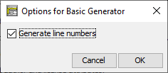
-
Generate line numbers on export:
BASIC (Beginners' All-purpose Symbolic Instruction Code) has developed numerous dialects from the very beginning. There are worlds between the first versions (about 1970ies) and some modern derivates with object-oriented enhancements etc. that hardly remind "good" old BASIC at all (Microsoft VisualBasic may serve as an extremely drifted-away example).
So it's nearly impossible to refer to BASIC as a specific language. Correspondingly, a code export to "BASIC" is somehow a joke. We try it nevertheless.
The option here partitions the BASIC world roughly into
- the ancient types with mandatory line numbers and very restricted subroutine support ("vintage" BASIC), e.g.
10 REM This is an example of early BASIC
20 LET C = 5
30 ...
- and some more up-to-date style without line numbers, but with some generalised variable declarations via "dim ... as ..." etc., e.g.
Rem This may serve as an example for modern dialects
dim C as Integer
C = 5
...
- Perl
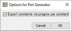
-
Export constants via pragma use constant (since version 3.32-20):
By default, constant definitions will simply be exported as if they were normal variables, i.e. without write protection, and the name would be prefixed according to the Perl syntax rules for variables throughout the code. An instruction
const PI ← 4 * atan(1)
would therefore simply produce a code line
$PI = 4*atan(1);.
If you activate the above option, however, the generator would instead insert the following code line, which employs the pragma "use constant", close to the beginning of the generated file:
use constant PI => 4 * atan(1);
In this case, the constant name would not be prefixed in the subsequent expressions of the code.
The option may cause inconsistencies in the code, though, since "use constant" works only if the constant value can be computed at compile time by Perl and there is no sufficient information for the code generator to decide whether this may be the case for certain expressions. The code generator guarantees at least that the "use constant" pragma is not applied to routine arguments declared as constants and constant targets of function CALLs.
- ARM

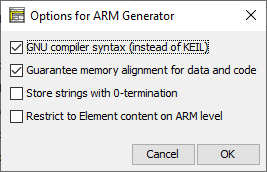
-
Code for GNU compiler (instead of KEIL):
By default, ARM code will be generated using the KEIL assembler language. By checking this option, GNU assembler syntax will be used for the export instead. GNU code does not only differ in the directives but even supports more features, e.g. output instructions, and can be used for embedded code in a gcc project (or for simulation in tools like CPUlator). Information about the syntax differences may be obtained here.
-
Ensure memory alignment of data and code (since version 3.32-03):
With this option activated, .align directives will be inserted before array allocations and the text section in order to ensure that the data object or code starts at an entire word address (or properly aligned according to the size of the array elements). This option has only effect in GNU mode where the allocation directives .byte, .hword, .word, .quad, and .octa do not automatically align the address (whereas KEIL directives DCW, DCD, and DCQ do align).
-
Store strings with 0-termination (since version 3.32-04):
Usually string literals will be stored as arrays of only the contained character code points without an additional terminating '\0' character (as in C strings). With this option enabled, however, the ARM generator will append a terminating 0 code on allocating strings.
-
Restrict to element content on ARM level (since version 3.32-05):
Though ARM generator may evolutionarily be made capable to compile more complex expressions and instructions than with the first prototype, in certain use cases (see section Special Syntax for ARM) it may be more desirable to restrict users (e.g. students) to instruction content that is compatible with the low-level capabilities of ARM processors (e.g. to reject expressions that contain more than one operator or more than one literal). This option is intended to force algorithm design on conceptional machine level and might be made predominant if desired. (Also see plugin-specific syntax checks in Analyser Preferences.)
- LATEX/Algorithm
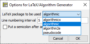
The Includes tab on the export options dialog allows to configure lists of files or modules formally to be included (or imported) by the exported code, i.e. on exporting a diagram to source code, the code generator will insert include directives, import or use declarations if there are some configured entries in the text field for the respective target language here:
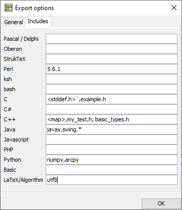
-
For a certain target language, fill in a comma-separated list of entities to be placed in include/import/use directives. What the entities mean and how the respective directive will look like depends on the target language. This configuration opportunity is thought for the case that you might produce a large number of diagram exports to a specific target language where always certain user-specifc file includes, module imports etc. would otherwise have to be inserted manually for each of them. The example above shows a version requirement for Perl that would look like
use 5.6.1;
in the produced code, whereas on C export you would obtain the two following lines near the top of the file (similar with C++):
#include <stddef.h>
#include "mumpitz.h"
On export to Java, the file would be forced to contain a line
import javax.swing.*;
(The generators are usually not capable of producing different kinds of directives for a single language — one might want to have both #include and using directives for C++, but the latter isn't supported.)
Note that in batch export mode you will have to specify a settings file containing them in order to achieve them being considered.
Further options may be added on user demand.
Note: Since version 3.30-11, all GUI-commanded code export features can be suppressed (i.e. they will vanish from the menus) via a line "noExportImport=1" in a central predominant ini file. This preference line can only manually be put into such a file (e.g. by means of a text editor).
9.11. Import options
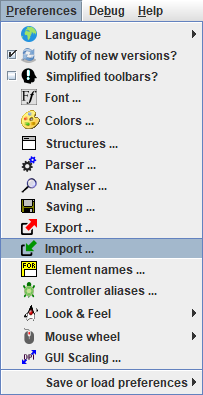
Menu item "Import ..." in the "Preferences" menu opens a dialog where options for the loading of files of different types may be configured:
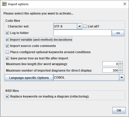
The dialog contains two boxes with options for the loading of
- code files (e.g. ANSI-C import),
- diagram files (Structorizer's own .nsd format).
What do the options mean:
- Character Set (for code file import)
You may control what character encoding to use on import. By default UTF-8 will be used but if you happen to find the import file encoded in a different caracter set then you may select the actual character set of the file in oder to import the code cleanly. While "List all?" isn't checked, the choice list will only offer you about six of the most common character sets. By enabling "List all?", however, the choice will be expanded to several dozens of encodings, i.e. to all your Java version will know of.
Note: For the moment this setting is of very limited use for files coded with an 8-bit-based character set, though, since the applied Pascal grammar doesn't cope with non-ASCII characters (apparently due to a parser bug) such that they have to be eliminated before actually starting to parse, anyway.
- Log to folder (for code file import, versions ≥ 3.27)
During parsing and diagram generation a log file will be written if this checkbox is ticked. Usually it is placed as <source_file>.log next to the imported source file. Here you may specify that all log files be directed to the specified folder instead (this is particularly helpful if the folder containing the source files is write-protected). With "." (single dot) you will direct the log files to the "current directory" (i.e., the last directory cached by Structorizer file-related actions). Button "<<" opens a directory selection dialog.
- Import variable (and method) declarations (for code file import, versions ≥ 3.27)
Since version 3.26-02, pure variable declarations (i.e. without immediate initialisation) in Pascal or VB syntax are tolerated as content of Instruction elements. Consequently, code import may optionally convert variable declarations found in the source code into declaring instruction elements in order to preserve original type information. To allow so, activate this checkbox. Since version 3.31-02, this option has an additional impact on Java and Processing import: The method declaration elements described in Java code import, will only be placed into the created Includable diagram that represents an imported class, if this option is chosen.
- Place configured optional keywords around conditions (for code file import, versions ≥ 3.30-07)
If this option is enabled then on importing IF statements, CASE statements, WHILE or REPEAT loops, then the conditions they contain will be decorated with the pre and post marker words currently configured in the Parser Preferences for the respective type of element. If e.g. an alternative is found in the code with a condition nTimes < 4 while the Parser markers for IF statements are specified as follows: Pre = "if" and Post = "?", then the resulting IF element will contain the text "if nTimes < 4 ?" rather than just "nTimes < 4".
- Save parse tree as text file after import (for code file import, versions ≥ 3.27)
The plugins doing the code import in Structorizer rely on an open-source LALR(1) parser in combination with a language-specific grammar. A successful parsing process results in a syntax tree of the input program from which the diagram is built. This parse tree may be delivered as text file <source_file>.parsetree.txt in the source directory. Just enable this option if you are interested in having a look at it or to clarify wrong or questionable import results.
- Maximum line length (for word wrapping) (for code file import, versions ≥ 3.28-11)
Specifies a number of characters per line, beyond which a word wrapping will split element text lines on import, i.e. where some atomic token (a word) of the text line would exceed the specified line length, the line will be split with a backslash at the end and the subsequent tokens will go to the next line etc. A value 0 means that no automatic word wrapping will be done.
- Maximum number of imported diagrams for direct display (for code file import, versions ≥ 3.28-05)
Some code files may contain a large number of functions and procedures. If hundreds of diagrams are pushed to Arranger, this was likely to have a massive degradation impact on the GUI response time:
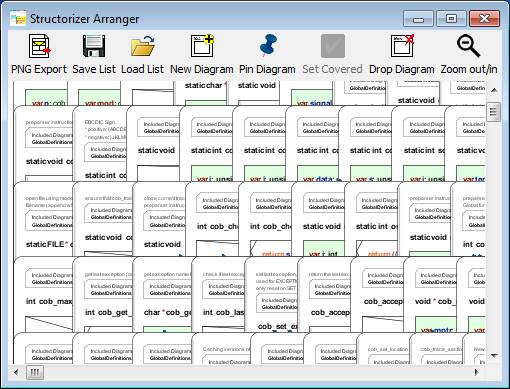
Though the underlying performance problems have eventually been solved with version 3.29-09, it may often be a better idea first to save all the imported diagrams to files and then to open and inspect them rather individually. Here is the option that allows you to specify the threshold number beyond which the diagrams are no longer placed in Arranger. Instead you will be offered to save the diagrams to the file system (or otherwise to discard them). The default threshold is 50. The maximum threshold for automatically accepted diagrams you can specify is 250.
Remark: This threshold does not apply for the loading of .arr or .arrz files and for dragging .nsd files into Arranger, nor does it prevent you from pushing diagrams from the Structorizer main form.
- Language-specific options (for code file import)
Besides general import options (as the ones described above) there are some very language-specific subjects to customization. These are plugin-specified and not hard-coded in the Import Options dialog. In order to configure those language-specific options
1. select the interesting import language via the choice box next to the button and
2. push the button "Language-specific Options"
to see what options are available for the respective import language and configure the relevant settings. Here are the settings currently specified:
- ANSI-C99

- Externally defined type names
C files may depend on type names introduced by included headers, which are not available for the C parser of Structorizer. The C grammar is very sensitive to type names, however. So you should list all type names causing parser errors in this text-field (separated by commas), thus allowing the Structorizer-internal preprocessor to make them digestible for the parser.
- Redundant pre-processor symbols or macros (versions ≥ 3.28-03)
Often, there are certain pre-processor defines in C with mere decalaratory effect, e.g. "WINAPI" in order to tell that a function definition belogs to the WinAPI or "_opt_in" as a pointer argument prefix indicating that this argument may expect a value (rather than being used to export values) or may be set NULL ("optional"). Pre-processor symbols like these are not only completely redundant for Structorizer import but would let the parser to fail. In this option you may enumerate names of this kind to be eliminated on import. You can also name parameterized macros that should be erased by appending parentheses to the name, optionally you may put the number of arguments in the parentheses (see image).
- Use type names and defines from WINAPI / MinGw (versions ≥ 3.28-05)
In order to import C code that uses e.g. WINAPI defines or those from MinGw, it would usually be hard to configure any single symbol, macro, or typedef used in the code via the text fields above (in a trial and error manner). Instead you may select the respective check box to provide the parser with the minimum required classification info about all defines of the respective library at once. They will neither override the text configuration fields nor be appended to them but made available behind the scenes. Be aware that it's not the full definition of the words but just helps the parser to let the source file pass.
- COBOL
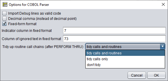
- Import Debug lines as valid code
Lines starting with ">>D" (free format, see below) or having an indicator symbol 'D' (in fixed format, see below) in COBOL are so-called debug lines specifying some code for debugging purposes. If the checkbox "Import Debug lines as valid code" is selected then these debug lines will be imported as active code, otherwise they will be converted to comments on import.
- Decimal comma (instead of decimal point)
It is possible that floating-point literals in a COBOL file use decimal commas (e.g. German locale) rather than the usual decimal points (e.g. British or US American locale). In order to make such a file pass the syntax analysis you must select this checkbox. (A file-internal directive with this regard is not recognised by Structorizer.)
- Fixed-form format
COBOL files may be formatted in the traditional fixed form (with fix column zones) or in free format (like most programming languages).
| Example for fixed-form COBOL |
Example for free-form COBOL |
 |
 |
The parser must know in advance what format the file is using unless a directive (" >> source format is free/fixed") in the first line of code specifies it (see example in the table above).
- Indicator column in fixed format
Even provided fixed format is used, there may be differences in the column where the classifying indicator characters are placed. Here you can specify at what column they appear in the specific file to be loaded (default is column 7). Just enter the column number.
- Column of ignored text in fixed format
As before, there is a certain column in fixed format, from which on the remaining text of the line is to be ignored by the parser. Default is 37. Enter the actual column number before importing a fixed-format COBOL file if it differs from 37.
- Tidy up routine call chains (after PERFORM THRU)
This mode (versions ≥ 3.32-09) addresses the import of PERFORM THRU statements. They refer to a code span between two given labels and thus generate a chain of calls to (parameterless) routines derived from so-called paragraphs or sections. Without tidying all thes calls (≥ 2) will be put in a single CALL element (which violates the rules for forming CALL elements but resembles best the original context. The multiline CALLs can easily be split by transmutation (magic wand  or <Ctrl><T>) but this tends to become a real hassle if the diagrams contain dozens of such CALLs. In addition, the last call of such a chain usually refers to a redundant routine, which contains only a disabled paragraph exit. The tidying mode now allows to control this behaviour and to facilitate the generation of clear and concise diagrams:
- tidy calls and routines (the new default) will automatically part the multi-line calls, remove calls referring to redundant routines and eliminate these routines as well;
- tidy calls only works as before but omits the elimination of the redundant routines (they will remain unreferenced in the arrangement group of imported diagrams), some of the referencing Calls my also just be disabled rather than removed;
- don't tidy does not do any tidying, which is less suited for easy import but may be helpful for "forensic" analysis of import problems concerning internal procedures. In this case special comments in the multi-line CALL elements will recommend the manual steps to tidy up the diagram (see COBOL import hints).
- Java SE 8 (versions ≥ 3.31)
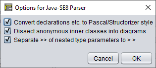
- Convert declarations etc. to Pascal/Structorizer style
This option configures the degree of the syntactical conversion. With this option selected, Structorizer would convert e.g. a variable declaration like int[][] matrix; to
var matrix: array of array of int
otherwise it would leave it more or less as is (keeping it more recognizable for Java programmers but less usable in Structorizer). If you intend to make an attempt to execute (debug) or re-export the resulting diagrams then it is strongly recommended to select this option.
Note that the general import option "Import variable (and method) declarations" also plays an important role for the contents of the resulting diagrams.
- Dissect anonymous inner classes into diagrams (versions ≥ 3.32.17)
This option procures that anonymous inner classes defined "on the fly" on instantiation like in the following example will be converted into local (sub)class diagrams. Without it, the defining code will be passed as is, i.e., as usually very long Java expression without translation, into the instantiating instruction. The option is by default enabled. Example (where a new anonymous inner class is derived from class WindowAdapter):
this.addWindowListener(new WindowAdapter() {
@Override
public void windowClosing(WindowEvent evt)
{
btnCancel.doClick();
}
});
The class in the derived diagrams will not of course be anonymous but obtain a generic name like e.g. WindowAdapter_5d880813. The instantiating instruction in the respective element would then be:

- Separate >> of nested type parameters to > > (versions ≥ 3.32.18)
The parser used to mistake a sequence of closing angular brackets as they occur with nested type parameters (like in HashMap<String>, List<Integer>>) for a shift operator, which makes an import fail. The option enables a heuristic preprocessing of the source file to tell right shift operators from clusters of right angular brackets and to insert blanks between the latter ones in order to let the code pass the grammar. This works pretty well but is not guaranteed to preserve all actual operators. If this should happen then you wouldn't have a chance to import the file unless you switch off this new option (which is by default active) and to insert the blanks between the clinging angular brackets manually.
- Processing (versions ≥ 3.31)
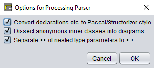
- Convert declarations etc. to Pascal/Structorizer style
See Java SE 8.
- Dissect anonymous inner classes to diagrams (versions ≥ 3.32.17)
See Java SE 8.
- Separate >> of nested type parameters to > > (versions ≥ 3.32.18)
See Java SE 8.
- Replace keywords on loading a diagram (NSD files)
As outlined in other sections of this manual, the interpretability of a diagram strongly depends on the parser preferences in particular, i.e. an input instruction will only be recognized if it starts with the currently configured input keyword etc. Hence, if you load a diagram created by someone else (or years before) then it is not unlikely that it adhered to a different set of parser preferences when it was saved. So the first thing you used to obtain in earlier versions was a lot of Analyser warnings. In order to sort them out you would either have to adapt the parser preferences to the diagram or vice versa. Which is both cumbersome or can even get nasty if you want to combine several diagrams of different origin by Calls.
To overcome this unpleasant situation, version 3.25-01 began to save diagram files with all non-empty parser preferences as attached attributes. This way, recent diagram files became prepared for this refactoring option:
With the checkbox enabled, Structorizer will replace all obsolete keywords throughout the diagram being loaded by the respective currently configured parser keywords, such that the diagram will automatically fit into your current context. (Actually, the diagram content will be modified to maintain its semantic equivalence.) The refactoring won't work with legacy NSD files originating from versions before 3.25-01, of course, because older .nsd files are lacking the decisive information. You would have to adapt them manually first and re-save them with a Structorizer of at least version 3.25-01 to benefit from the refactoring mechanism. (For this manual refactoring, however, you should benefit from the Find & Replace tool.)
It is highly recommended to enable this import option. Only if you are sure never to be confronted with diagrams originating from a different preferences context or if you need to see the originally used keywords then you may leave this option unchecked. You will even be warned when a diagram with differing keyword set is loaded while the refactoring mode is switched off, e.g.:
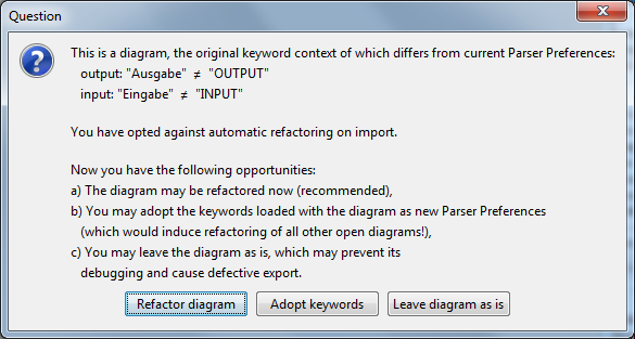
You may now choose among the three offered opportunities. If you opt for c), i.e. to postpone a measure then the first attempt to modify the diagram later on will pop up a slightly different dialog (since version 3.27):
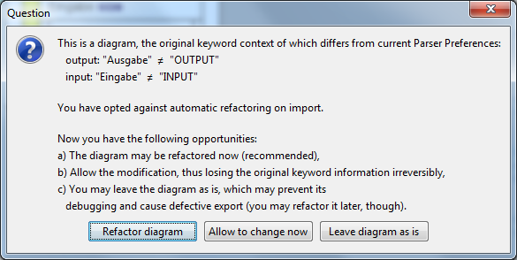
Now the postponed refactoring may eventually be done (such that the editing will be based on a consistent content) or the keyword information may be abandoned in order to do all changes manually. Last but not least, the change may be cancelled (option c) and hence the solution of the problem would be postponed further.
On applying "Save as..." to an (unchanged) diagram with postponed refactoring the original keyword set will be saved instead of the current Parser Preferences. After a forced diagram modification, however, the original keyword set will irreversibly be lost in Structorizer.
Further import options may be added in future versions on user demand.
9.12. Element names
The Problem
The algorithmic standard elements each Nassi-Shneiderman diagram is composed of are of course referred to at many places of the graphical user interface (GUI) of Structorizer: in menus, dialogs, and messages. The elements must of course be named somehow. These names are subject of localization i.e. per chosen language there will usually be a different set of designations. The localization is not always complete, looks sometimes un-natural, is not necessarily unique and sometimes not even consistent. Moreover, it is not always welcome to everyone. Many users feel more comfortable with the familiar English concepts.
By means of the Translator tool, you could of course derive an individual translation file from the respective locale shipped with Structorizer. But this is tedious, not only because of the many occurrences of element names in the locale files. An additional complication is: Whereas in general any accomplishment proposal sent to the developers (particularly for those locales that have fallen behind the functional development of Structorizer) is highly welcome, this may be of little help in this specific field of element names where conflicts are likely.
The Solution
Structorizer now offers you to configure your favourite naming of element types in an easier and more sustainable way (since version 3.27-04). Such individually specified labels will override the localized names from the locale, independently of the chosen language.
In order to configure your individual designation set, select the menu item "Preferences › Element names ...":
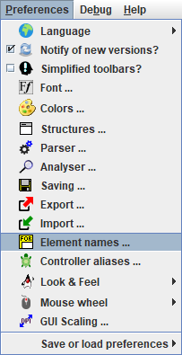
This menu item will open the Element Names Preferences dialog (see following screenshot). In the left column, the localized names of the element types and flavours according to the currently chosen language are listed. In the right column, there is a text field for each of them where you may enter your preferred name. You may leave some fields empty, in which case the respective name on the left side won't be overridden (but be aware that this will hold for any chosen language):
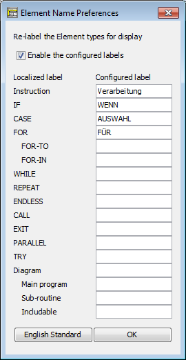
The text fields are only editable while the checkbox "Enable the configured labels" is selected. The second effect of this checkbox is that it enables (or disables, if unselected) the actual name replacement in the GUI texts. The following screenshots of a menu and a dialog demonstrate the effect of the example above (after having enabled the configured element labels):
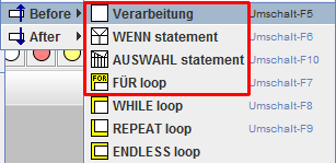
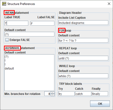
If you disable the configured labels (uncheck "Enable the configured labels"), then the specified names won't get lost but remain there inactively such that the replacement may be re-enabled whenever this seems opportune.
Lest unaware users should be irritated, the checkbox will automatically be unselected whenever you change the locale (i.e. switch to another language via menu "Preferences › Language"). But as soon as you turn the mode on again, the replacements will immediately be effectuated, no matter which language you are in. Well, this is not quite true because some of the locale files haven't been prepared yet to support this feature.
Since version 3.29-11, a button at the bottom of the Element Name Preferences dialog fills in the standard English element type names (i.e. the English designations of the algorithmic structures) when pressed:
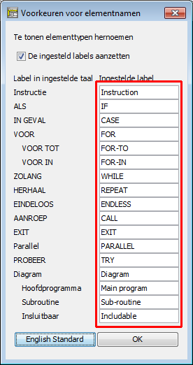
This way, the graphical user interface will always show the (internationally understood) English names, no matter what locale is selected. Yet you will still have to switch the checkbox on after changing the locale (see previous paragraph).
The Mechanism
To achieve the behaviour described above, the message retrieval mechanism was modified in a way that partially uncouples the labelling of elements from the remaining locale. Therefore, a new place holder mechanism was implemented where text translations should no longer directly contain localized element names but only specific markers to be substituted by the currently valid names for the related kind of element. These place holders start with a '@' character and may have a short or long form. In the short form, just a lower-case letter follows, whereas in the long form the successive key is an internal element class name enclosed in braces. While functionally equivalent, the somehat cryptic short form is more performant in message retrieval, whereas the long form is obviously more readable. In the following Translator screenshots, two locale files (the English and the Spanish one) use the short form whereas the French locale uses the long form:
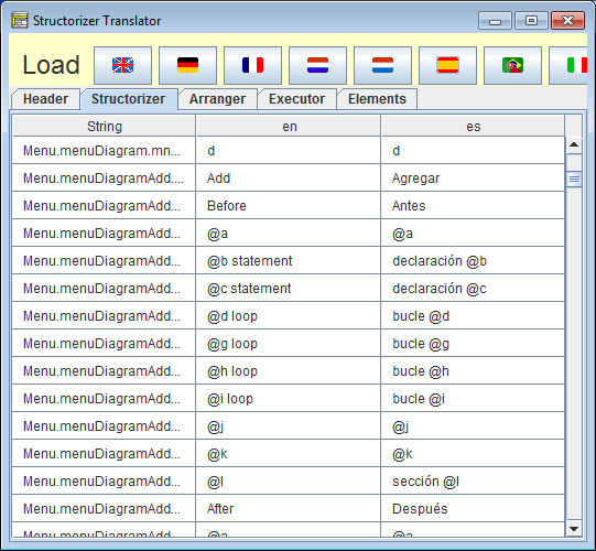
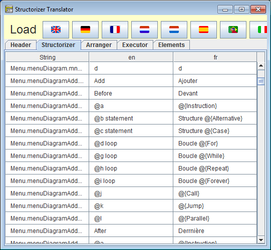
The localized element names themselves are now concentrated in a separate section / tab of the locale file rather than strewn redundantly all over the messages:
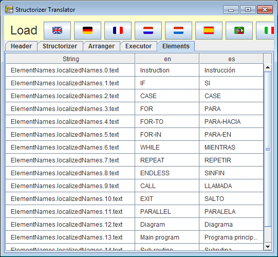
(In some cases and with some languages, however, this simple mechanism may cause trouble with grammar.)
The comment section in the language file headers contains an explaining legend:
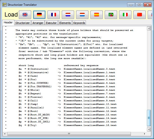
The user-specified element names use the same place holder mechanism but aren't stored in the locale files. Instead they reside in the "structorizer.ini" file in the user home directory.
Summary: Whenever a message contains an element name place holder (@...) then a three-stage substitution policy is applied:
- If user-defined element labelling is enabled (see above) and the name field for the respective kind of element is filled in then this designation will replace the place holder.
- Otherwise, the element type name from the locale file will be inserted (if specified).
- If neither a user-configured nor a localized name is available then the name from the English product locale will be used (fallback).
9.13. Controller Aliases
Motivation for Alias Routine Names
Built-in routines of a programming environment have normally a fix name and a given argument order. If you don't adhere to these "details", they simply won't work...
So in order to compute e.g. the square root of some number x, where there is a function sqrt for, you will have to use sqrt(x), whereas "square_root(x)" won't of course work.
With some plugged-in demo controller modules like Turtleizer, this is now (i.e. since version 3.27-05) different: Teachers requested a possibility to "translate" (more generally: to rename) the available turtle commands in order to facilitate the learning process of their pupils, such that e.g. users in Spain might type "adelante" instead of "forward" in order to move the turtle ahead.
But these alias names should not automatically change with the chosen dialog language. So a separate preferences mechanism was needed.
The Controller Alias Specification
Version 3.27-05 introduced an additional preferences dialog available via menu item "Preferences › Controller Aliases ...":

When selected, the following dialog will appear where you may specify your favourite alias names for the available routines of plugged-in controller modules (by now there is only Turtleizer, but some day there might be more):
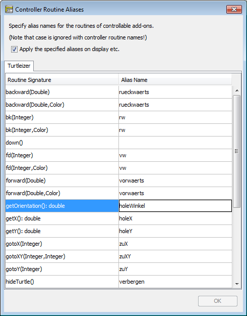
The dialog contains a tab for every plugged-in diagram controller module with a lexicographically sorted table of all available procedures and functions. The left column shows the original signatures (i.e. names, expected argument types, and the result type — if the routine returns a value). The right column is initially empty, but you may fill in your favourite alias routine names, which are virtually to replace the original names. Don't write parentheses and type names there, just the alternative routine name. Argument number and types cannot be changed. The alias names must be identifiers, i.e. they must only consist of (English) letters, digits, and possibly underscores, like this_is_4_you. Other characters like spaces, hyphens, operator symbols, or special alphanumerical characters (e.g. ä, ú, ß) must not occur. Otherwise your typed name will be rejected:
The dialog does not only check identifier syntax but also that there won't be name conflicts among the controller routines. This check is only done when you press the "OK" button or try to leave the dialog with <Ctrl><Enter> or <Shift><Enter> (which also mean committing the changes). If the combination of an alias name with the argument number of the associated routine equals some original routine signature or another specified alias (case-ignorantly), then an error message listing all conflicting sets of routines will pop up and tells you to resolve the listed conflicts (by choosing other names or by clearing conflicting aliases):
You may use the same alias name for routines with different argument number, though, but not for routines with equal argument numbers.
(By the way, the conflict list is sent to the system clipboard when the "OK" button of the above message box is pressed such that you might save it somewhere and have a look at it while you modify the conflicting names.)
An empty cell in the right column means "no alias" for the routine of that row. So by clearing a cell you can delete a specified or conflicting alias.
If you leave the dialog with <Esc> or by pressing the close button ([x]) then all your changes will be discarded (forgotten).
The Effects
In order to make the alias definitions effective you must select the checkbox "Apply the specified aliases on display etc." above the tab region in the Diagram Controller Aliases dialog (see screenshot farther above).
If you do so then the defined alias names will immediately replace the original routine names in the rendering of the diagram and on editing:
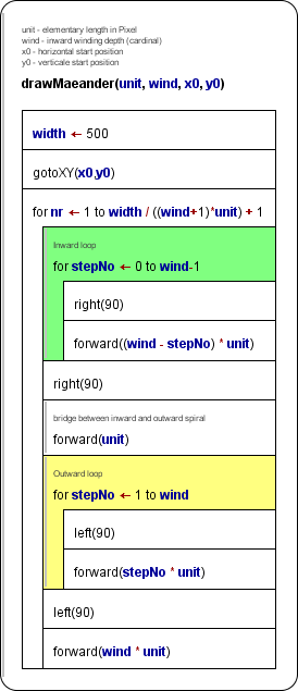
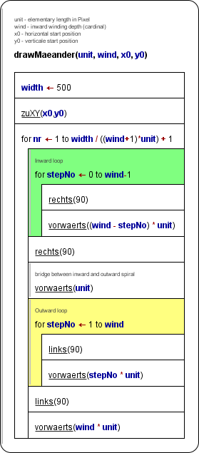
In syntax highlighting mode, the alias names will be underlined for easier distinction.
In the element editor you may type either the original or the alias name without making a difference: The diagram will constantly show the alias, and when you edit a respective element, you will find the alias in the editor text area.
Internally, however, the original routine names are still stored in the diagram, such that execution, code export etc. are not affected, i.e. they work as before. This way, you will even see loaded diagrams with your set of aliases if they have been created without any alias or with a different set of aliases.
9.14. Look & Feel
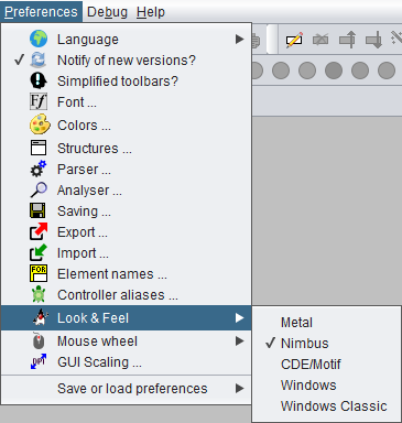
Here you can change the overall look & feel of the graphical user interface of Structorizer. The different designs that appear in the submenu are those that are installed on your computer. Simply select one of them. Structorizer remembers the chosen theme and will load it automatically the next time you start Structorizer.
Here are four L & F examples of some part of the Diagram menu (ijn order of appearance: "Metal", "Nimbus", "Motif", "Windows"):
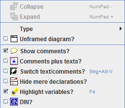
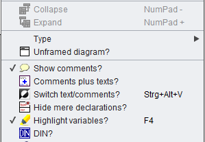
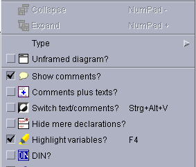
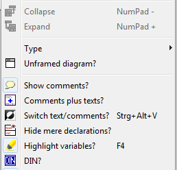
(The screenshots throughout this User Guide were taken with different Looks & Feels.)
Hints:
- If you ever happen to come to a situation where the given design makes Structorizer crash (i.e. prevents opening it), then open the file structorizer.ini, which is located in the subfolder .structorizer of your home directory, with a text editor that copes with UNIX newlines, seek the line starting with "laf=" and delete it. Then start Structorizer again.
- The "CDE/Motif" Look and Feel may have some unexpected side effect. So the usual Cut, Copy and Paste hot keys (Ctrl-X, Ctrl-C, Ctrl-V) won't work within the Element editors, but the UNIX-like equivalent actions like central mouse-button click in order to paste may not work, either. Usually, Shift-Del, Ctrl-Ins, Shift-Ins (also being very common in Windows) may work instead, though. Likewise the size of the controls on some dialogs may vary so much that e.g. the OK button might not be visible without manually enlarging the respective dialog.
- See GUI Scaling if — besides the Look & Feel — the size of your icons or GUI fonts does not please you or e.g. if you want to scale up Structorizer including menus, toolbars etc. for presentation purposes.
For further details about "Java Look & Feel", please "google" yourself ...
9.15. Mouse wheel
In the "Preferences" menu you can specify what effect the mouse wheel is to have within Structorizer:
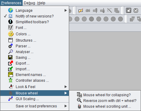
The submenu " Mouse wheel" comprises two toggle items and another menu item for functional aspects of the mouse wheel (or the analogous wiping gestures on a touchpad):
-
 Mouse wheel for collapsing?
This toggle item concerns only the behaviour within the Structorizer work area (see overview). If it is selected then rolling the wheel within the Structorizer work area will collapse or expand the currently selected element(s). Otherwise rotating the mouse wheel will simply scroll in the Structorizer work area vertically or (on most platforms) — with the <Shift> key pressed — horizontally. For other scrollable contexts (Arranger, Arranger index, Analyser report area, Output Console, etc.) this setting has no impact at all. Even in the work area the normal scrolling may be effective with a little delay though the collapsing is enabled.
 Reverse zoom with ctrl + wheel?
This toggle item addresses a behaviour introduced with version 3.28-01: Rotating the mouse wheel with <Ctrl> key pressed zooms in (on upward rotation) or out (on downward rotation) in the following scrollable contexts: Structorizer work area, Arranger, and Output Console. Though this is the usual (and intuitive) zoom effect, there are some applications that have an inverse mouse wheel zooming. So if you happen to be accustomed to the reverse zooming effect, you may select this menu item to accommodate. Mouse wheel scroll unit ...
The menu item allows you to accommodate the scrolling speed (i.e. the basic scrolling unit for the mouse wheel) in a range between 1 and 20 (since version 3.29-09, the larger the number the faster the scrolling). The impact concerns both the diagram work area in Structorizer and Arranger. On selecting this menu item a small dialog with a spinner will pop up, so just modify the number and test the effect:
9.16. GUI Scaling
Structorizer is not DPI-aware, i.e. it will not automatically magnify its icons and fonts with very high screen resolutions (like e.g. 4K). This ought to be done by the GUI framework, actually, but JavaSwing fails to do so, at least it had done so before Java 9.
Therefore Structorizer offers at least a somewhat makeshift workaround among the preferences. It is based on a configurable scaling factor. This offered a useful side effect, e.g. for beamer presentations in classrooms. So maybe the functionality will prevail even though future releases might rely on the fixed DPI capabilities of Java (versions 11 and above).
Via menu item "Preferences › GUI Scaling ..." you may preset and test a scaling factor for the Structorizer GUI:
In the dialog opened via the menu item you may preset a scaling factor for the Structorizer GUI, which will be valid from the next Structorizer start on:
The three "Preview" controls on this dialog grow with the selected scale factor, thus demonstrating how the result would look like. For scale factors < 2.0, no direct proportional scaling but a "size variant" mechanism of the Look & Feel is used, which may not be supported by all Look & Feels on any operation system. If an appropriate icon variant with higher resolution is available, then this will be used, otherwise the icons will simply be scaled (magnified), which may result in blurry, rough-looking or strangely pixeled images. Make sure that the scaled check box reacts to clicking (test it here!), otherwise you should try with a different Look & Feel for the wanted scale factor:
When you start Structorizer next time, all icons should be magnified by the pre-selected scale factor. The effect, however, may still strongly depend on:
- the operating system (Linux / OsX / Windows /...);
- the computer- or platform-specific display settings;
- the selected Structorizer Look & Feel.
With certain Look & Feel / OS combinations, some of the fonts might resist the scaling attempt. In other environments, the scaling may differ among various controls or it may even be unstable (such that e.g. certain tab or sub menu captions switch their font size on being selected). Title bars would usually not be affected (as their appearance is controlled by the OS), whereas checkboxes at menu items might remain in tiny (i.e. standard) size despite of the magnification of their corresponding captions. Or the checkbox might not properly react to the user activity (some Look & Feel might e.g. show the box checked while and whenever the cursor is hovering over it).
The scaling consistency has been improved substantially between Release Structorizer 3.26 and version 3.26-01, though in upscaled mode some L&F-specific effects (e.g. "mouse over" shading) may still get simplified or even lost.
So, don't expect too much, please. You might have to experiment a little in order to find out which Look & Feel (and what scale factor) works best for your purposes, machine, and taste.
Note:
- Version 3.25-08 introduced the additional opportunity to enlarge or diminish the font sizes in the element editor text fields by "fontsize up" and "fontsize down" buttons
 (also achievable via key strokes <Ctrl><Numpad+> and <Ctrl><Numpad-> while the focus is within one of the enabled text fields), respectively:
This enhancement had to be introduced because on some systems the fonts for these text fields cannot be controlled by the general scaling factor.
- The GUI scaling factor does not affect the font of the element and comment texts within the diagrams, neither in the work area nor in Arranger. The diagram font is to be controlled separately via the Font preference or the toolbar buttons
 . The diagram element sizes depend directly and only on the diagram font.
10. Import
Structorizer allows to derive Nassi-Shneiderman diagrams from source files of some programming languages and also to import some flowchart or Nassi-Shneiderman diagram files originating from other tools.
10.1. Source files
Source Code Import
Structorizer allows to derive a structogram from a given source code file (reverse engineering). By now, this import feature is only available for CLI Pascal, C (ANSI-C99), Java (SE 8), COBOL, and Processing files, other programming languages are likely to follow.
Be aware that the grammars used by Structorizer for parsing the source code are usually somewhat simplified, and you might face parser errors with some correct code samples, which are simply too complex for a reverse engineering or contain peculiarities Structorizer may not cope with anyway. In particular, Structorizer cannot sensibly import so called "spaghetti code". This means code that makes use of GO TO instructions or other means of the source language not being compatible with the idea and concepts of structured programming. Code with pointers will pass the syntax analysis but the resulting diagrams won't be executable because Executor doesn't support pointer types. You may have to experiment with some language-specific Import Preferences or manually pre-process such code files (e.g. cut some parts out, modify others) in order to be able to import at least the essential algorithmic structure. See also section Troubleshooting.
In interactive mode, you can import code files of any supported programming language just by dragging the corresponding sources onto Structorizer. The respective parser will automatically be selected based on the file name extention. If the decision is ambiguous then you will be presented a choice menu to select the most appropriate parser.
Another way to achieve the same goal is to use the menu, i.e. "File › Import › Source Code ...".
In the file chooser dialog that will open you may select the appropriate file filter (combobox at the bottom of the dialog), both to restrict the search and to disambiguate the parser choice:
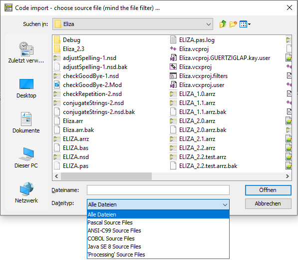
If the name extension of the selected file does not match the file filter of any of the available parsers then a choice dialog will open requesting to associate the intended parser (via the related file filter) or to cancel:
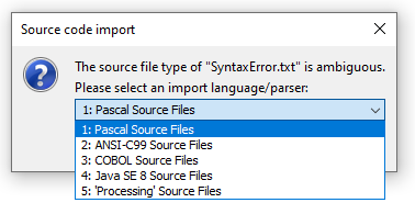
The importer will parse the file according to a provided grammar and, if that has succeeded, synthesize control structures from the derived parse tree. Certain control keywords (or standard function names) of the source language recognized in the instruction texts may be replaced by the corresponding parser preferences for the same structures, as currently configured.
A code import monitor shows you what phase the import process is working in and the rough progress:
This way it may look like on the completion of an import:
The monitor allows you to abort the import process via the "Cancel" button:
If an error occurred then you will get a similar picture but with the information that errors occurred (after accepting you would be shown the error description in a separate window, see further below):
The import of a single file may produce many diagrams (one for each function or routine plus some diagrams for shared stuff). These diagrams will be poured into the Arranger unless their number exceeds a configurable limit (see Import Preferences):
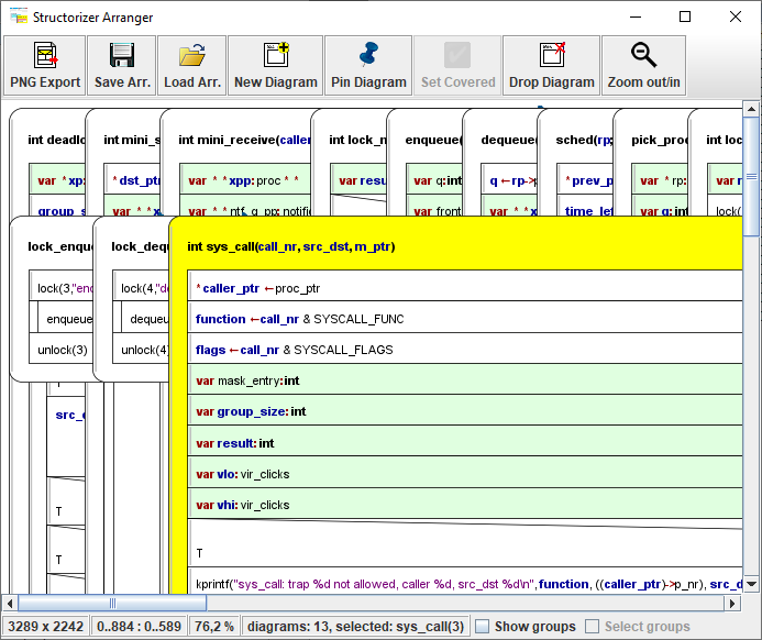
If the limit is exceeded, you will be offered to save the diagrams instead and only the assumed main or most important diagram will be displayed:

When you select the target directory and accept the proposed name or specify a different name for the first of the files, you may opt for automatic acceptance of the name proposals for all remaining files via an "accessory" checkbox on the right-hand side of the file chooser dialog:
If you would overwrite an existing file you will yet be warned and may freely decide to modify the name, to overwrite the old file, to skip this file, or to cancel the serial saving activity. (This opportunity will always occur if you use the "Save All" menu item or button with several files never having been saved.)
Note: Since version 3.30-11, a mode with all interactive code import opportunities being disabled (they don't even appear in the menu) is achievable. To activate this mode, do the following:
- A structorizer.ini file is to be placed in the installation directory as predominant ini file, which must contain a line "noExportImport=1" (manually to be inserted e.g. by means of a text editor).
- Other settings in this file are not necessary unless they shall be predominant.
Syntactical Restrictions
Pascal Code Import
Note that Pascal files to be imported must have a program, unit, package, or library header. If you want to convert a bare subroutine (procedure or function) definition you have to embed it in one of these sorts of compilable concepts before, e.g. in a unit or between
program dummy;
and
begin
end.
Since version 3.32-18, even some ObjectPascal / Delphi 7 sources may be imported producing half-way sensible sets of diagrams. Because Nassi-Shneiderman diagrams were not designed for OOP, some dirty tricks had to be used to present classes and methods in a reasonable way. See Java import for the taken compromises, which apply here in a similar way. (Analyser will of course complain about almost everything in the resulting diagrams.)
C Code Import
C source files should not make excessive use of externally defined preprocessor symbols like __stdcall, __thiscall, or __cdecl. You may, however, declare such symbols as "redundant" defines in the Import Preferences such that they would be removed automatically before the actual parsing begins.
NOTE: Release 3.30 removed the deprecated ANSI-C73 parser, which had very inconvenient syntactical limitations, e.g. it did not accept the reserved word "unsigned" alone (without subsequent scalar type name like "int" or "short") as typename. Source code containing function pointers could not be parsed, either.
COBOL Code Import
COBOL file import is a somewhat delicate task. First make sure that the format (fixed-format or not) of the file is correctly chosen in the COBOL-specific Import Preferences. The syntax of the language is very peculiar, some of the strangest constructs may not have been implemented in the import.
Certain types of statements may require manual or, optionally, automatic postprocessing, e.g. PERFORM THRU instructions are primarily converted to multi-line CALL elements (which cause Analyser warnings) and will therefore have to be split into single calls and cleaned up afterwards. By default this is done automatically after the import, but the COBOL-specific Import Preferences offer you the choice among three modes of assistance. If you decline automatic tidying then specifically inserted comments will suggest you sensible steps for tidying-up (since version 3.32-09):

The generated diagrams may also contain functionless (and therefore permanently disabled) marker elements (derived from the CALL element type, see there for examples) showing you e.g. the places of paragraph or section labels in the COBOL code (where subroutine code may have been extracted) or indicating COBOL statements that exceeded the capabilities of Structorizer import (the latter ones usually in signal red).
Another example for import deficiencies: Some COBOL expressions like X IS ALPHABETIC-LOWER without direct functional equivalent in Structorizer will be transformed into expressions with function syntax but no executional backup (here: isString(x) and isAlphabetic_lower(x)) in order to convey the meaning.
Java Code Import (since release 3.31)
Most Java source files can be imported if they comply with Java SE 8 syntax and don't make use of lambda expressions. There are some syntactical pitfalls, however:
- The closing angular brackets of nested type arguments used to cause syntax errors if there is no space between them (they were mistaken for shift operators), e.g. in
HashMap<String, Stack<Integer>> doesntWork.
Version 3.32-18 introduced an import option "Separate >> of type parameters to > >" to automatically insert spaces between right angular brackets were they belong (but sparing actual shift operators) in the file preprocessing phase. The option is by default active. In some cases, however, it might compromise >> or >>> operators. If this happens to be a show stopper then you should switch the option off and insert the blanks manually instead until the parsing succeeds.
- Empty type parameter lists, as e.g. in new ArrayList<>(Arrays.asList(values)), will automatically be removed before the parsing. In certain cases the same may happen for unspecific type parameters like in Class<?>[].
- Annotations are not in all positions accepted where the Java language specification allows them. As they are of no importance in Structorizer, you might simply remove or outcomment them before the import.
- Anonymous internal classes like in the following code snippet will only be converted into diagram elements if the Java-specific import option "Dissect anonymous inner classes into diagrams" (introduced with version 3.32-17) is enabled. Otherwise the code would simply be placed as expression (i.e., more or less as is) into the surrounding context element (here an Instruction element):
BaseClass b = new BaseClass(){int doSomethingDifferent(int a){return a * 13;}};
You should not expect the diagrams resulting from Java code import to be executable in Structorizer — Java is too deeply OOP-based, we can't provide a sufficient class context —, only limited efforts were made to convert the Java source style to the syntactic preferences in Structorizer (in the Import Options, there is a Java-specific checkbox to configure the degree of syntactical conversions, however). It would have alienated the content too much without significantly improving the chance to run/debug the diagrams. The major benefit of a Java import is assumed to be its graphical structure representation, and this is what it satisfies. Java classes will be represented by Includable diagrams. They are put to the include lists of all member diagrams (classes or methods) to potentially allow them access to the fields declared as constants or variables in the class-representing Includables. In order to address the hierarchical nature of Java classes (with member and local classes etc.), a "namespace" attribute was added to the diagrams, which is filled on Java code import with the package path (on top level) or the respective class / method name prefix (on nested levels), such hat the Arranger index can present the class path. If not empty, then even the editor for diagrams will show (and allow to manuipulate) it:
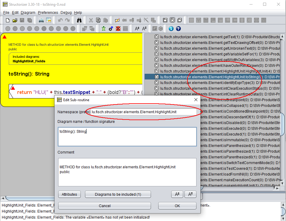
A checkbox menu item "Show qualifiers as prefix" in the context menu of the Arranger index allows to switch off the display of the "class paths" (see screenshot for the Processing import below). Instead, the hierarchical relations between the diagrams would then be represented as a multi-level tree (which costs more update time, though):
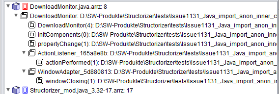
In addition to the subroutine diagrams, which are representing methods of a class, the respective method diagram headers (the declarations) are also inserted as permanently disabled pseudo-CALL elements (if the general import option "Import variable (and method) declarations" is selected). In order to improve legibility the inner text areas of these diverted CALL elements will not be hatched (in contrast to usual disabling) since version 3.32-20. These pseudo-CALLs serve just as sort of links to the method diagrams — via the menu entry "Edit Sub-routine ..." you can summon the referenced diagram into an additional Structorizer window for inspection:
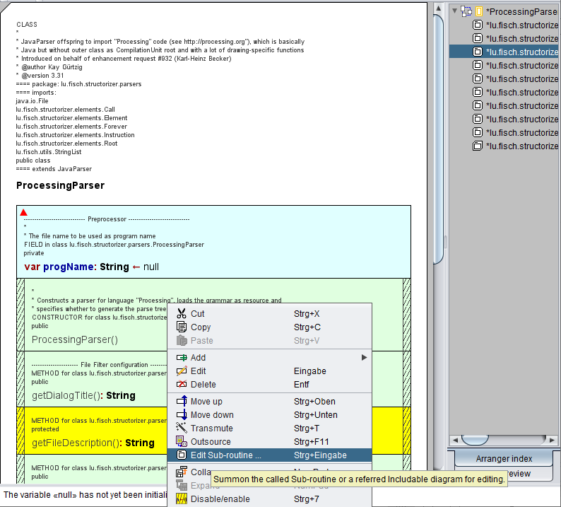
As mentioned above, you may opt out of their import (together with mere variable declarations). You may of course also simply remove the declarations after having imported them, or you could hide them via display mode  Hide mere decarations.
Processing Code Import (since release 3.31)
Processing source code is like Java code with an implicit class on top level and a set of built-in functions and variables, which may be regarded as methods and fields of that implicit outer class. Other than Java, it is not an all-purpose language but dedicated to 2D and 3D graphic presentations. No main method is required to start. Instead, a setup() method is implicitly called as initialization. Then a method draw() is run in an implicit eternal loop after the initialization. On the import to Structorizer, the latter reflects the usual Processing behaviour by placing the respective calls into the top-level Includable and a related program diagram (see screenshots below for an example from the language reference).
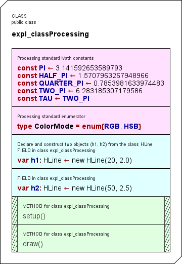
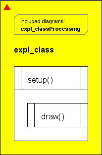
Structorizer reflects some of the standard "Processing" constants in the Includable diagram (see above, way more of them since version 3.31-03, now placed in a separate Includable diagram). If the imported code contained individual classes, they will be represented in analogy to the Java import with hierarchy-reflecting qualifiers in the Arranger index. (Via the context menu, the qualifier prefix display may be switched off and give way to a deep tree representation instead):
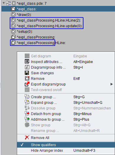
The Processing parser still does not cope well will import directives at the beginning of the code. So better comment them out before you try to parse a pde file.
Subroutines / Methods
A file comprising several routine definitions (or a class with several methods) will be converted into a set of separate diagrams, one for each of the routines, and — if not empty — another one for the main program. If you do the import within the application (rather than as batch job, see below) then the imported diagrams will be collected in the Arranger (if the configurable diagram number threshold as introduced with version 3.28-05 isn't exceeded).
Be aware that subroutine calls (references to other functions) can only be identified as such by Structorizer if the corresponding routine definitions are also available in the imported code. Otherwise the respective lines of code will usually be inserted as ordinary Instruction elements but may manually be transmuted to equivalent CALL elements (at least if you intend to run the algorithm with Executor). This element transmutation, however, can be done by a simple mouse click. The capabilities of identifying standard routines or library functions for which there would be analogous built-in routines in Structorizer are still rather poor. (But improvements are planned.)
Definitions and Declarations
Type definitions (particularly for record/struct types) and constant definitions may be essential for the interpretability of expressions. Therefore they will be imported (since release 3.27). In the resulting diagram set, they will occupy Instruction elements, possibly in Includable diagrams, as they are usually needed globally. Constant definitions will be converted to assignment instructions (typically dyed in rosé and equipped with a comment "constant!" by the respective parser). Initialized variable declarations will also be imported as assignments.
The import of mere variable declarations (i.e. without initial value assignment) may be enabled via the Import Preferences dialog. Imported (local) declarations will typically be coloured in a faint green. (Since version 3.26-02, declarations in Pascal or VisualBasic style are tolerated as content of Instruction elements.)
When you import a class (Java or Processing) then method declarations may be added to the Includable diagram that will represent the imported class. These are permanently disabled elements shaped like a CALL and referencing the respective method diagrams. The creation of these method reference elements depends on the same import option as for variable declaration import.
Comments
The import of comments may also be enabled via the Import Preferences dialog. Structorizer tries its best to associate comments found in the source code to the closest element they may belong to.
Note: Some code files as exported from Structorizer might cause errors on re-import if they haven't been completed manually before. (Watch out for TODO or FIXME comments in the generated code.) Declaration sections e.g. in Pascal export frm earlier Structorizer versions might only contain comments, but Pascal source files are not allowed to contain empty declaration areas (e.g. a var keyword without variables being declared after it).
Global and Shared Stuff
Note: Global declarations and initialisations (e.g. from C source files) will be placed into so called Includable diagrams, which are referenced in the "include list" of the main program diagram (if one emerged from the file) and those routine diagrams that refer to them. Additionally, global declarations will be presented in a light cyan background colour after import. The C import will only support a minimum subset of the C pre-processor (simple #defines without arguments); #include and #if in any variant may NOT be expected to work. If the code strongly depends on them then you may run the C source code through your compiler's pre-processor (for example gcc -E) and import the pre-processed source in order to compare the results or pass the parser restrictions.
Troubleshooting
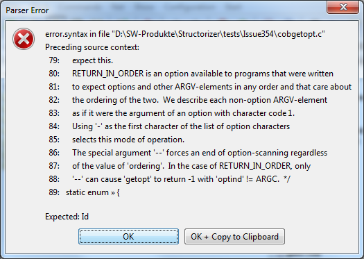
If the code to be imported is not compatible with the used import grammar then you will be presented an error dialog as shown above where always the last 10 lines of code are shown for better orientation — for the line numbers might not exactly match those of the original code because usually some problematic pieces of the source may have been cut off in a preprocessing phase. In the last line, a little arrow symbol (») indicates the character or token where the parser detected a problem. As usual, the parsing failure may actually have been caused by preceding parts of the code. The message box also tells you what kind of symbols the parser had expected. For a deeper analysis you may inspect the import log file placed in the folder of the imported file. Its name is automatically derived from the source file itself.
Often it is an iterative process to get complex source files imported where you may have to modify some import options step by step in order to overcome certain problems (and bump into others). Sometimes it may even be necessary to modify the source file.
If you always get errors on import of apparently correct source files then the parser log file placed next to your source file (if enabled) may be helpful in the analysis. It contains the tokens read during preprocessing, possibly some token report emerged from the actual parsing, and the tried reduction rules during the build phase. In case of an error the error message will also be present here. Maybe the content doesn't say you so much but if you request help from the developer team then the parser log file will be highly appreciated.
If the pre-processing succeeds but the parsing constantly fails, such that you assume that a defective preprocessing causes the troubles, then the preprocessed intermediate source file can be very helpful. You may find it in your temp directory (location is OS-dependent). It is named
"Structorizer<cryptic_hex_number_sequence>.<extension>"
where <extension> is the source-file-specific file name extension (e.g. "c", "pas" or the like). Date and time of the file may help to identify the relevant one.
Third helpful kind of file is the parse tree file in case the parsing succeeded but the diagram builder causes trouble.
Last but not least consider the general log file being situated in the .structorizer folder of your home directory. Look for the most recent (or least out-dated) log files. You may have to close Structorizer in order to obtain a flushed file.
See Import Preferences in order to find out where you may enable the respective logging.
Batch Import
Structorizer may also be used in batch mode to convert a source file (Pascal, C, or COBOL) into an NSD file or, morwe typically, into a set of NSD files or an arrangement archive. The command syntax is given below, where the underlined pseudo program name Structorizer is to be replaced with the respective batch or shell script name for the console environment:
- structorizer.sh for Linux, UNIX, and the like;
- Structorizer.bat for Windows.
The scripts can be found in the downloadable Structorizer zip packages (you always need these for batch command); don't try with Structorizer.exe!
Structorizer (-p|--parse) [parser-name] [-f] [-z] [-e encoding] [-l max-line-length] [-v log-directory] [-s settings-file] [-o output-file] source-file ...
The options mean:
-p (or, equivalently, --parse, with versions ≥ 3.32-23) must be the first option and indicates the use as parser, i.e. for code import. Unless you provide an explicit parser-name, Structorizer will conclude from the file name extensions what code parser is to be used. This holds on a file-per-file basis, i.e. the source-file list may even be hetergenous, say it may contain mixed Pascal, C, and COBOL files for whatever parsers will be available.
If you (optionally) specify a parser-name next to the -p switch then this will override the automatic parser detection and try to parse all files listed with this parser — no matter what file name extensions they may have (since version 3.28-05). The currently available parameter values for parser-name are (where '|' separates synonyms; ANSI-C73 aka CParser was withdrawn by release 3.30, Java-Se8 and Processing were introduced with release 3.31):
- Pascal | D7Parser
- ANSI-C99 | C99Parser
- COBOL | COBOLParser
- Java-SE8 | JavaParser
- Processing | ProcessingParser
-e (followed by a charset name) is reserved for the choice of the source file character set (for Pascal import it's still rather irrelevant, though, because the used Pascal grammar doesn't cope with any non-ASCII characters, such that these are simply eliminated in a pre-parsing step).
-f forces overwriting an existing file with same name as the designated output file (see -o), otherwise an output file name modification by an added or incremented counter will be done instead (e.g. output.nsd -> output.0.nsd), thus preserving the existing file.
-l (followed by a non-negative number) specifies after how many characters a text line should be broken (wrapped) in order to avoid too long lines. The line wrapping respects syntactical units like string literals etc. (it is sort of a word wrapping). If zero is specified then automatic line breaking will be suppressed. If this option is not specified then the line limit from the import preferences held in the structorizer.ini file will be used.
-o (followed by a file path or name) specifies the output file name. If not given, the output file name will be derived from the source file name by replacing the file name extension with ".nsd". The file name extension ".nsd" is ensured in either case. If several source files were given then without option -o the nsd file names will be derived from the corresponding source file names; with option -o, however, the name variation described for the absence of option -f would be used (creating files output-file.nsd, output-file.0.nsd, output-file.1.nsd etc.). If several diagrams emerge from a source file then the respective function signature will be appended to the base original file name, e.g. output-file.sub1-0.nsd, output-file.sub2-4.nsd etc.
-s (followed by a text file path) specifies a settings-file to be used used for retrieval of general and parser-specific options for the import. (Without switch -s the application defaults would be used.) The file must contain relevant key=value pairs, where the keys for parser-specific options are composed of the parser name and a corresponding import option name, both glued with a dot, whereas general import option keys start with "imp", e.g.:
C99Parser.definesToConstants=true
COBOLParser.fixedColumnText=37
impComments=true
Since version 3.29-12, you may configure import options in Structorizer GUI and save just these import options to a specific ini file, see Preferences export and import. So you won't any longer have to look for the relevant keys among the randomly ordered key-value pairs in the abundant structorizer.ini file like for a needle in a haystack and then copy the strewn lines to your import setting file. Of course you can modify the values with a text editor in the selectively saved ini file without changing your settings residing in structorizer.ini. (Usually, you will adhere to the settings held in structorizer.ini, though, which is maintained via the Structorizer Import Options dialog).
-v (followed by a directory path) induces that for each imported file source-file a corresponding log file log-directory/source-file.log will be created in the specified folder, where preprocessor, parser and diagram builder write their log data into ("verbose mode"). These log files might help diagnose parser trouble.
-z specifies that in case a source file induces more than one diagram file (typically if the source contains several routines) a compressed arrangement archive (with file name extension .arrz) is generated instead of loose files (since version 3.29-09). In this case, only the archive file will inherit the source file name (or the outfile name specified with option -o), the diagram files within the archive will have file names as proposed by the created diagrams, i.e. derived from the diagram name or subroutine signature.
If option -z is not specified then at least an arrangement list file (with the name of the source file or the out file and extension .arr) will be produced for each set of diagrams emerging from one source file (as far as they are more than one). This way, it is very convenient to load the connected diagrams at once into Structorizer or Arranger.
source-file (one or many file paths/names) stands for the code files to be parsed and converted to Nassi-Shneiderman diagrams (nsd files).
Examples:
structorizer.sh -p testprogram.pas
The above Linux/UNIX command imports file "testprogram.pas" from the current directory as Pascal source and will create the resulting nsd file with name "testprogram.nsd" (if it is a single diagram).
Structorizer.bat -p -e UTF-8 -o quicksort.nsd qsort.pas
This MSDOS command imports file "qsort.pas" (from the current directory) as UTF-8-encoded Pascal file and stores the resulting structogram in file "quicksort.nsd".
Structorizer.bat -p -e ISO-8859-1 -v . foo.c bar.cob
This MSDOS command parses the source files "foo.c" (as C file) and "bar.cob" (as COBOL file), assuming both to be encoded with ISO-8859-1 character set, storing the resulting diagrams by default as "foo.nsd" (plus possibly "foo.0.nsd", "foo.1.nsd", etc.) and "bar.nsd" (plus possibly "bar.0.nsd", "bar.1.nsd", ... etc.) in the current folder. It also writes log files "foo.c.log" and "bar.pas.log" to the current directory (option "-v .").
10.2. Foreign diagrams
Foreign diagram import
Structorizer allows to import Nassi Shneiderman diagram files generated by other free diagram editors:
- "Struktogrammeditor" (.strk files, since version 3.27),
- "hus-Struktogrammer" (.stgr files from the Java version since 3.29-13, .stgp files since version 3.32-08),
- "sbide" (.sbd files, since version 3.32-07).
(All of them are alternative free editors for structograms, developed by Kevin Krummenauer, Hans-Ulrich Steck, or Johannes Kässinger, respectively, not necessarily all open source, though. Whereas sbide is a browser tool, the other products are Java applications.)
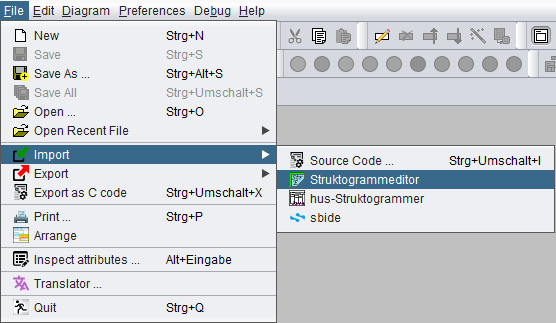
To import diagrams emerging from one of these editors is quite straightforward: Select the respective menu item
- "File › Import › Struktogrammeditor",
- "File › Import › hus-Struktogrammer", or
- "File › Import › sbide"
(see screenshot above) and use the popping-up file chooser dialog to elect the .strk, .stgr, .stgp, or .sbd file you want to import. As a result you will obtain a structurally equivalent Nassi-Shneiderman diagram (or an arrangement from a .stgp file) in Structorizer. On importing a hus-Struktogrammer project file, the name of the resulting group will be derived from the project title string or (if that is missing) from the file name.
(Note that an import of .stg files as emerging from the Delphi-based Stgr32 version of hus-Struktogrammer has not been implemented, but there is a simple workaround: You may use the Java version of hus-Struktogrammer to open them and convert them to equivalent .stgr files, which will be importable in turn. The import of hus-Struktogrammer project files of type .stgp became available with version 3.32-08.)
Usually, the text content of the imported diagram elements is not tried to interpret on import. It will mostly be imported as is. (So it may not be conform to the Executor-compatible Structorizer-specific syntax recommendations, input and output instructions may not be recognized as such, etc.)
- On hus-Struktogrammer import at least some redundant default text prefixes like "While" or "In the case of" may be removed automatically if NSD import option "Replace keywords on loading a diagram (refactoring)" is enabled.
- For sbide diagrams the situation is slightly better: declarations, operators and keywords are adapted. Even an array index transformation is tried because the index base in sbide is 1, whereas it is 0 in Structorizer and many programming languages. (In the resulting diagram, all affected elements, i. e. those which contain an index access on declared array variables, will be equipped with a comment "Caution: array index base was adapted!" to allow for consistency checking.)
(A PapDesigner flowchart import is also intended.)
11. Export
Created Nassi-Shneiderman diagrams can be exported to several file formats.
- Export to graphics output formats is described in section Picture.
- Textual formats, chiefly programming language source code export is treated in section Source code.
- Certain flowchart formats, described in section Flowchart.
11.1. Picture
Interactive Export as Picture
Via the menu "File › Export › Picture..." you may create image files of your Nassi Shneiderman diagrams in several image file formats.
Currently the following formats are supported:
PNG files are exported with transparent background (since version 3.24-15).
On exporting to PNG, you may split the image of a (large) diagram into a matrix of several files. After selecting menu item "PNG (multiple) ..." you will be asked for a number of columns and a number of rows. The file names will then be generated with a two-dimensional numbering, making clear how the image is divided into the tiles and which file contains what part. Both row and column index are added as two-digit decimal numbers counting up from 00, e.g. if you selected a file name "myDiagram.nsd" and decided to split the image into a matrix of 2 columns and 3 rows, then the files would be named and associated to the image sections according to the following scheme:
| myDiagram-00-00.png |
myDiagram-00-01.png |
| myDiagram-01-00.png |
myDiagram-01-01.png |
| myDiagram-02-00.png |
myDiagram-02-01.png |
To compensate rounding problems, the files of the last column and the last row may be some pixels larger than the others lest there should be losses.
Note: Prior to release 3.25, the generated files in mode "PNG (multiple) ..." were continuously numbered row by row, columns first, e.g. if you exported an NSD with name "myDiagram.nsd" and decided to split the image into a matrix of 2 columns and 3 rows, then the files would have been named and associated to the image sections according to the following scheme:
| myDiagram-0.png |
myDiagram-1.png |
| myDiagram-2.png |
myDiagram-3.png |
| myDiagram-4.png |
myDiagram-5.png |
Batch Picture Export (versions ≥ 3.32-23)
From version 3.32-23 on, Structorizer may also be used in batch mode to generate picture files of certain graphics or document file formats from NSD or arrangement files. The command syntax is given below, where the underlined pseudo program name Structorizer is to be replaced by the respective batch or shell script name for the console environment:
- structorizer.sh for Linux, UNIX, and the like;
- Structorizer.bat for Windows.
The scripts can be found in the Structorizer installation directory; don't try with Structorizer.exe! (Even while a Java WebStart installation had still been supported it did not provide them — you need the unzipped downloadable version.)
Structorizer (-i|--image) filetype [-s settings-file] [-o output-file] nsdarr-file ...
The command will usually generate one picture file for every diagram (.nsd) and arrangement (.arr, .arrz) file listed as arguments.
Unless a specific settings file (.ini file) is specified via option -s, the diagram drawing preferences (view, font, parser and other related preferences from the personal ini file for the Structorizer installation will be applied.
The options mean:
-i or --image (followed by a file extension as listed below) must be the first option and selects the target file format (or file type). Currently supported file formats are (case-insensitive):
-o (followed by an absolute or relative folder path) specifies a non-default output folder. Without option -o the output file name(s) and locations will be derived from the respective .nsd , .arr, or .arrz file name by replacing the name extension with the one associated to the target file format, e.g. ".png". With option -o, however, the specified folder will be used as common target folder for all output files. If the last path component is a name not specifying an existing folder (but new or associated with a simple file) then this name will be ignored and the (existing) parent folder will be the target folder. Be aware that Structorizer will always force the file name exension specified in the -i/--image option. The -o specification will be ignored if the path does not exist, i.e., cannot be used without having created the required subfolders before.
-s (followed by a text file path) specifies a settings-file (i.e. some .ini file) to be used used for retrieval of drawing-relevant view-specific settings and e.g. parser preferences. (Without switch -s the preferences from the user-specific .ini file would be used.) The file ought to contain the relevant key=value pairs, otherwise the respective application defaults would be used.
Since version 3.29-12, you may prepare suited option in Structorizer GUI and save just the relevant option categories to a specific ini file, see Preferences export and import.
nsdarr-file is the file path of a Structorizer diagram (.nsd) or an arrangement file (.arr or .arrz) to be drawn into a file. It might also be a so called Arrangement file specification. An arrangement file specification consists of an arrangement file path (.arr, .arrz) with an optionally appended sequence of diagram names or routine signatures, separated with exclamation marks (no blanks!), e.g.
- D:\workspace\tests\bar.arr!MAIN!sub(2-3)!test(7)
- '/home/bob/files/foo.arrz!test(7)!MAIN!sub(2-3)'
In case diagram names or signatures are given, then only the specified diagram subset of the arrangement will be included into the graphics content.
Note: It is possible that an arrangement file was not the result of saving an arrangement from Arranger but the result of e.g. batch code import. In this case, the positions of the diagrams in the arrangement may be unset, which causes Structorizer to draw all contained diagrams at the coordinate origin, i.e. one on top of the other. In batch mode, Structorizer will not detect this and not rearrange the diagram to avoid overlapping. You might consider loading the .arrz file into the interactive Structorizer (in order to arrange the diagrams sensibly and then saving the resulting arrangement again.
11.2. Source code
Code Export Preparations
First of all, if you want to use the code generators, you should make sure to have filled in the parser preferences appropriately. You can find them via the menu "Preferences › Parser ...":

All the words you filled in there will be filtered out and replaced by the respective target language keywords.
For example, if your diagram contains a FOR loop and you are writing french diagrams, you may have something like this:

If you then do a "Pascal" export, the generated code will be:
for I:=1 to 10
begin
{ do something }
end
whereas a "C" export will result in the code:
for (I=1; I<=10; I+=(1)) {
// do something
}
As you can notice, the words "pour" and "à" have been eliminated or replaced with whatever the exported code requires. For being able to do this, the generators must be fed the necessary information about the syntax you are using in your diagrams.
Interactive Code Export
Menu
To export the current diagram in the work area as code, go to the menu and select "File › Export › Code ›" and the name of the language you want to export to. (In case these menu entries happen to be missing, see Export Configuration note.)
The currently supported programming or script languages are the following ones (where StruktTeX and LaTeX/Algorithm are not actually a programming languages but related to LATEX add-ons providing embeddable NSD drawings or pseudocode illustrations, see Export Preferences for examples of the latter):
- Pascal / Delphi
- Oberon
- Perl
- ksh
- bash
- C
- C#
- C++
- Java
- Javascript
- PHP
- Python
- Basic
 ARM
ARM- StrukTeX
- LaTeX/Algorithm
You may also start the export from the Code Preview via the context menu.
Note the general export configuration opportunities and in particular that some of the languages (actually Basic, ARM, and LaTeX/Algorithm so far) may have additional generator-specific options.
Group Export
Another way to export source code from a diagram or even an entire arrangement group is to use the context menu of the Arranger Index. Having selected a group or a single diagram in the list, you may start the export via menu item "Export diagram/group ›" and the name of the language you want to export to. (If this menu item happens to be missing in a version ≥ 3.30-11 then it is likely to be due to an export/import suppression mode, see Export Configuration note.)
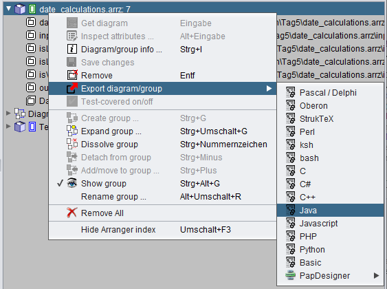
Group export allows to generate libraries consisting of several public routines, which are not necessarily referencing each other. If the group had to be partinioned then you will get the following information:

Export Configuration
In the Export Preferences you may select your most frequently used (favourite) target language in order to accelerate the export via key combination Ctrl+Shift+X:

You should be aware, of course, that the generated program files may usually not immediately be compilable or executable in the target language but require some manual post-processing because the generators will have to do a lot of mere guesswork: Though Structorizer tries hard to derive static type information from assignments or implicit declarations, the types of many of the used variables will not be known such that the generators will hardly be able to produce complete declaration lists for languages that require strict declaration. You will have to check for wrong, missing or mis-placed declarations and must accomplish or correct them manually. Some algorithmic construct may not directly be translatable such that the generators must try their best to compose something closely equivalent.
Usually "TODO" comments inserted in the generated code will guide you through the manual post-processing work.
The Export Option "No conversion of the expression/instruction contents" allows you to perform a kind of raw export with mere control structure conversion and mostly suppressed translation of the element contents. It is recommended to use this option if you explicitly write target code in Structorizer elements. In this case Structorizer wouldn't know how to translate your code into any other language, though.
Export Option "Involve called subroutines" is to enrich the code for the selected diagram with the routine definitions for all subroutines referred to by contained CALL elements and all includable diagrams referenced in the include list — if the corresponding diagrams are reachable via the Arranger. This works recursively. Unavailable subroutines the exported diagram depends on will be reported without aborting the export process (the definitions will simply be missing in the resulting file(s)). You may find hints for missing subroutines in advance in the Analyser Report List if Analyser Preference "Check for inappropriate subroutine CALLs and missing call targets" is enabled. Or, if the diagram itself has been arranged, you may check stale references via the Arranger Index:
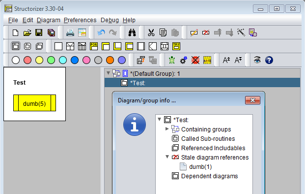
See also: Code generators.
For a complete list of export configuration preferences see Export Options.
Note: Since version 3.30-10, Structorizer can be started in a mode with all interactive code export opportunities (including code preview) disabled. It is intended for certain teaching and examination situations. The way to activate this mode differs between version 3.30-10 and later versions, however:
- In version 3.30-10, this was temporarily achieved by adding a parameter "-restricted" to the command line used to start Structorizer (e.g. within the "program shortcut" on Windows).
- From version 3.30-11 on, instead a structorizer.ini file is to be placed in the installation directory as predominant ini file, which must contain a line "noExportImport=1" (manually to be inserted e.g. by means of a text editor). The "-restricted" command line parameter as of version 3.30-10 is no longer supported.
Batch Export
Structorizer may also be used in batch mode to generate source files for a supported programming language or other textual export format (like StrukTeX) from NSD files. The command syntax is given below, where the underlined pseudo program name Structorizer is to be replaced by the respective batch or shell script name for the console environment:
- structorizer.sh for Linux, UNIX, and the like;
- Structorizer.bat for Windows.
The scripts can be found in the Structorizer installation directory; don't try with Structorizer.exe! (Even while a Java WebStart installation had still been supported it did not provide them — you need the unzipped downloadable version.)
Structorizer (-x|--export) generator [-a] [-b] [-c] [-k] [-l] [-t] [-e encoding] [-s settings-file] [-] [-f] [-o output-file] nsdarr-file ...
The command will by default generate a common code file from all the diagram (.nsd) files listed as arguments. The original idea behind this behaviour arose before arrangement (.arr, .arrz) files have become processable and was to allow the batch production of a consistent source file from a related set of diagrams, without access to an Arranger context. For separate conversion of diagrams the command could simply be executed in a loop. Code generation for arrangement files (.arr, .arrz), which had later been allowed as members of the file list, will always be held separate. Since version 3.32-10, a new option -k in a way simulates a command loop internally, i.e. keeps the code generation for the listed .nsd files separate as well.
Note that the export configuration you may have performed in interactive mode is practically null and void for batch export, you must specify the wanted modes via command line options described below (-a, -b, -c, -l, -t, -s in particular).
The options mean:
-x (or, equivalently --export with versions ≥ 3.32-23), followed by a generator or language name, must be the first option and selects the target language. Currently supported language specifiers are (case-insensitive, synonyms separated by "|"):
- PasGenerator | Pascal | Delphi
- OberonGenerator | Oberon
- PerlGenerator | Perl
- KSHGenerator | ksh
- BASHGenerator | bash
- CGenerator | C
- CSharpGenerator | C#
- CPlusPlusGenerator | C++
- JavaGenerator | Java
- JsGenerator | Javascript
- PHPGenerator | PHP
- PythonGenerator | Python
- BasGenerator | Basic
- ArmGenerator | ARM
- TexGenerator | StrukTeX
- TexAlgGenerator | LaTeX | Algorithm
-a ensures that the diagram metadata attributes like author, creation time, and license text or link will also be exported as comments into the code file(s).
-b sets the opening block brace (C-like languages) for the body of compound statements at the beginning of the next line (otherwise to the end of the same line).
-c will export simple instruction texts as comments (sensible if the diagram contains rather pseudocode than executable expressions).
-k keeps the export of the listed Structorizer diagram files (.nsd) separate from each other and preserves their names for the produced isolated code files (as if the command would have been executed for each one of them in a loop; since version 3.32-10). Before and without this switch the translations would always be amalgamated into a single code file (just "scissor lines" labelled with proposed file names would mark the positions where the diagram-specific code could be cut). The source files will be placed in the folder(s) of the respective source .nsd files, unless option -o specifies otherwise (about the combined effects of options -k and -o see table below).
-l will create line numbers on BASIC export (in this case more ancient-style code at the same time) and LaTeX/Algorithm export (not for all supported packages in the same way, thow).
-t will suppress most transformations of instruction and expression contents (intended for the case that the Structorizer elements already contain code complying with the target language syntax).
-e ("encoding", followed by a charset name) determines the output file character set (UTF-8 being the default).
-f forces overwriting an existing file with same name as the designated output file (see -o, -k), otherwise name conflicts will be solved by an auto-incremented number suffix (e.g. output.cpp → output.0.cpp).
-o (followed by an absolute or relative file/folder path) specifies a non-default output file name or just an output folder. Without option -o the output file name(s) and locations will be derived from the first listed .nsd file name by replacing the name extension with the one associated to the target language, e.g. ".java". With option -o, however, the filename specified there will be used to control the target folder and possibly the file name. If the path behind -o (including its last path component!) designates an existing folder then it determines just the target folder for all output files while the base names are chosen as per default. If the last path component is a name not specifying an existing folder (but new or associated with a simple file) then this name will be used for the common export result of the listed .nsd files in the target folder. (For arrangement files this does not hold, their code result will always be named after the arrangement file but also be placed in the target folder suggested by the -o option.). Be aware that Structorizer will always force a standard file name exension according to the target language (i.e. add or replace it). The -o specification will be ignored if the path does not exist, i.e., cannot be used without having created the required subfolders before. See table below for the combined effect of options -o and -k (from version 3.32-10 on).
-s (followed by a text file path) specifies a settings-file (i.e. some .ini file) to be used used for retrieval of general and generator-specific options for the export. (Without switch -s the application defaults would be used.) The file must contain relevant key=value pairs, where the keys for generator-specific options are composed of the generator name and a corresponding export option name, both glued with a dot, whereas general export option keys start with "genExport", e.g.:
BasGenerator.lineNumbering=true
genExportComments=true
Since version 3.29-12, you may prepare suited export options in Structorizer GUI and save just these export options to a specific ini file, see Preferences export and import. So you won't any longer have to look for the relevant keys among the randomly ordered key-value pairs in the abundant structorizer.ini file like for a needle in a haystack and then copy the strewn lines to your import settings file. Of course you can still modify the values with a text editor in the selectively saved ini file without changing your settings residing in structorizer.ini. (Usually, you will adhere to the export settings held in structorizer.ini, though, which is maintained via the Structorizer Export Options dialog).
- (single minus sign) will direct the code to the standard output instead of to the default output file. If -o option is also given, then the result will be written both to standard output and to the specified output file.
For some of the above options (i.e. the binary ones), the respective upper-case letter has the exactly opposite effect (e.g. -L would switch off the line numbering even if a specified settings-file specifies otherwise, i.e. explicit switches have priority over file-based settings, also see below).
nsdarr-file is the file path of a Structorizer diagram (.nsd) or an arrangement file (.arr or .arrz) to be converted into source code. Since version 3.29-05, it might also be a so called Arrangement file specification. An arrangement file specification consists of an arrangement file path (.arr, .arrz) with an optionally appended sequence of diagram names or routine signatures, separated with exclamation marks (no blanks!), e.g.
- D:\workspace\tests\bar.arr!MAIN!sub(2-3)!test(7)
- '/home/bob/files/foo.arrz!test(7)!MAIN!sub(2-3)'
Note that (single or double) quotes around such an arrangement file specification are strictly necessary with UNIX/Linux shells! Such a specification induces that program diagram MAIN and routine diagrams test (with 7 arguments) and sub (with two mandatory arguments and another optional one) will be picked out of the arrangement bar.arr or foo.arrz, respectively, as entry points (export roots) and exported together with all directly or indirectly referenced subroutine and includable diagrams from this archive into a single file. If no signatures are appended then all program (main) diagrams in the arrangement file will be taken as entry points (export roots). All contained diagrams will serve as potential entry points in this case. (Before 3.30-07 this had been different: You had to specify routine signatures if there weren't any program diagrams in the arrangement, otherwise nothing would have been exported from the arrangement.)
Without option -k, all "loose" .nsd files among the file arguments will contribute their diagrams to a single common source file, which is divided by "scissor lines", i.e. comment lines looking like this:
"=== 8< ===================================".
You may have to cut the file at these scissor lines in order to form a compilable project.
Each arrangement file, however, will feed a separate own source code file. It may consist of several modules, then also separated by "scissor lines" (see above). The first of these modules will usually be a "library" containing all definitions and routines commonly required by more than one of the identified entry points, the following modules represent an entry point each with all their individual requirements out of the arrangement. You may have to cut the file apart at these scissor lines and name them individually. If the scissor line is labelled with a file name then this module should get the respective file name (due to dependencies), all remaining file snippets may be named more or less arbitrarily.
Be aware that:
- the parser preferences configured in interactive Structorizer mode will be valid here, whereas
- the export options configured in interactive mode are null and void for batch export. Unless command line option -s explicitly specifies some .ini file as source for export options, only the command line options described above will be observed (for binary options, the contrary of the described option effect being the default, e.g. without specifying -l option there won't be line numbers or other old-fashioned relics in BASIC output). For export option "Involve called subroutines" a specific rule applies: It will automatically be enabled for arrangements and disabled for loose diagram files.
Examples for the combined effects of options -k and -o: Imagine there is an existing folder /home/alice/src. Then the folllowing table shows the expected effects of different command variants:
| Command | Resulting files |
Structorizer.sh -x Python a.nsd b.nsd g.arrz /diagrams/c.nsd |
./a.py (containing code from a.nsd, b.nsd, /diagrams/c.nsd)./g.py (containing the code from g.arrz)
|
Structorizer.sh -x Python -o /home/alice/src a.nsd b.nsd g.arrz /diagrams/c.nsd |
/home/alice/src/a.py (containing code from a.nsd, b.nsd, and /diagrams/c.nsd)/home/alice/src/g.py (containing the code from g.arrz)
|
Structorizer.sh -x Python -o /home/alice/src/code a.nsd b.nsd g.arrz /diagrams/c.nsd |
/home/alice/src/code.py (containing code from a.nsd, b.nsd, /diagrams/c.nsd)/home/alice/src/g.py (containing the code from g.arrz)
|
Structorizer.sh -x Python -k a.nsd b.nsd g.arrz /diagrams/c.nsd |
./a.py (code from a.nsd)./b.py (code from b.nsd)/diagrams/c.py (code from /diagrams/c.nsd)./g.py (code from g.arrz)
|
Structorizer.sh -x Python -k -o /home/alice/src a.nsd b.nsd g.arrz /diagrams/c.nsd |
/home/alice/src/a.py (from a.nsd)/home/alice/src/b.py (from b.nsd)/home/alice/src/c.py (from /diagrams/c.nsd)/home/alice/src/g.py (from g.arrz)
|
Structorizer.sh -x Python -k -o /home/alice/src/code a.nsd b.nsd g.arrz /diagrams/c.nsd |
Same as before (last part of -o path will be ignored with -k) |
Structorizer.sh -x Python -o /home/alice/src/code g.arrz |
/home/alice/src/code.py (from g.arrz)
An arrangement file result will only adopt the name if it's the only element of the list. |
Export of Diagrams for Turtleizer
If you export diagrams that control Turtleizer, then the exported code will usually not work unless you find some more or less compatible source package for your target language. The Python language fortunately contains a native "turtle" package that fully supports all Turtleizer commands and functions. Since version 3.28-10 the Python code generator of Structorizer performs all necessary conversions and places the required import clause automatically. For Java and C++ you may easily get identical or equivalent external Turtle support:
- For Java, the original Turtleizer package sources from Structorizer are available for separate download and may be integrated in the Java project you set up around your exported code. You will also need the diagrcontrol package as an interface it relies on. Both packages require at least Java 8 as platform. The exported Java file will automatically be prepared to work with this package.
- For C++, there is a functionally equivalent VisualStudio project Turtleizer_CPP available on GitHub that can at least be used by console applications under Windows -- either as static library (after having updated the project file to your VisualStudio version) or simply by integrating the header and code files in your C++ project. (The project will also have to import the Windows library gdiplus.lib in the latter case.) Your exported C++ file will just have to include the "Turtleizer.h" header and possibly to append a Turtleizer::awaitClose(); instruction (provided the other project settings are suited, see the README.md file in the download or on the project page for details).
11.3. Flowchart
Since version 3.30-07, a diagram export to files readable by foreign flowchart editors became possible. The first supported file format is .pap, an XML-based represenation of flowchart projects in PapDesigner, a handy and very intuitive flowchart editor developed by Friedrich Folkmann. It is proprietary software but free of charge. Whereas recent versions (up to v2.2.0.8.04) used to reject all .pap files not saved by PapDesigner itself (because of a specific cryptographic checksum), its newer versions (from v2.2.0.8.06 on, most recent is v2.2.0.8.08) are capable of reading the .pap files produced by Structorizer, too, which are not checksum-secured.
The export can be done ...
-
for the currently edited diagram (possibly involving all called and included subdiagrams according to export option "Involve called subroutines") via menu item "File › Export › PapDesigner":
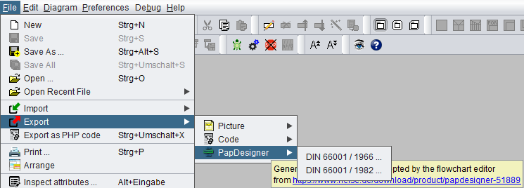
-
for an arrangement group or an arranged diagram (again regarding export option "Involve called subroutines") via the context menu of the Arranger Index:
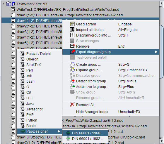
The two export variants offered by the submenu items "DIN 66001 / 1966..." and "DIN 66001 / 1982..." refer to different versions of the German standard DIN 66001 dating back to the years 1966 and 1982, respectively. Whereas the earlier standard had two different flowchart symbols for input and output but no specific loop symbols (loops had to be composed by decision symbols and cyclic links), the later version of the standard introduced specific loop start and loop end symbols but no longer accepted particular input and output symbols (it suggested the use of ordinary rectangular operation symbols for I/O activities instead).
Example:
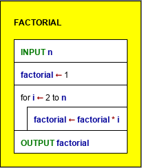
The export of this simple program computing the factorial of a cardinal number n looks as follows in PapDesigner, exported according to the respective DIN standard:
PapDesigner representation of the exported diagram
| DIN 66001 / 1966 |
DIN 66001 / 1982 |
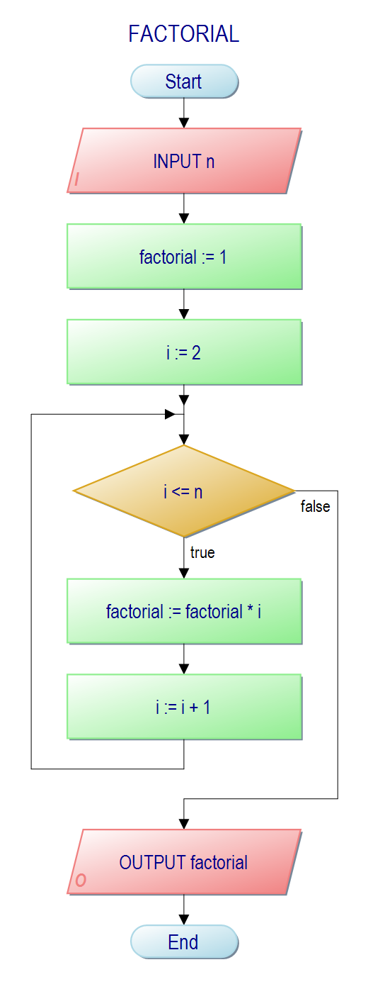 |
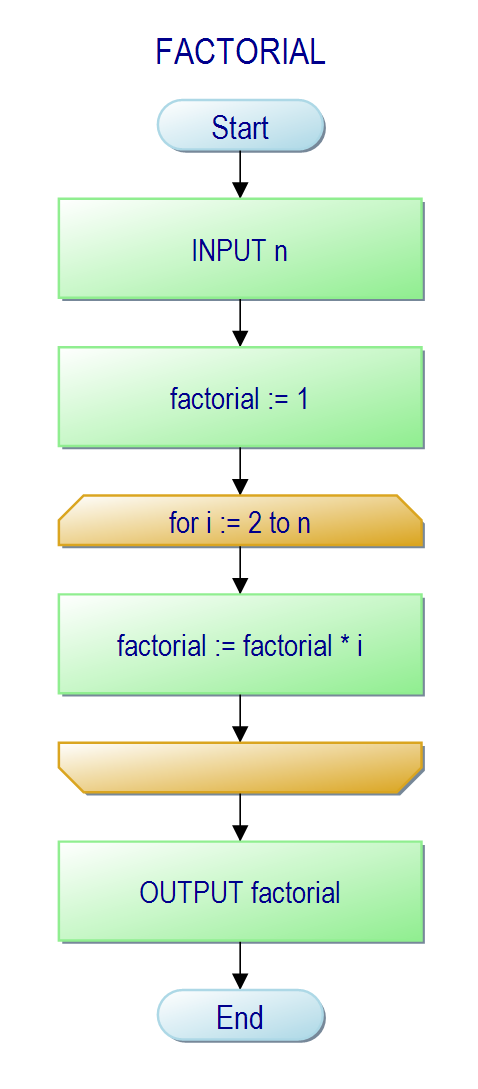
|
Some element types like EXIT, PARALLEL, and TRY cannot sensibly be represented on export to PapDesigner, though. Whereas for PARALLEL and TRY elements some surrogates enclosed in specifically marked loop start / loop end pairs are generated, the (temporary) workaround for EXIT elements uses blind connectors. CASE structures will be decomposed into a cascade of simple decisions (though PapDesigner even allows multiple branching of an outgoing link of a decision symbol):
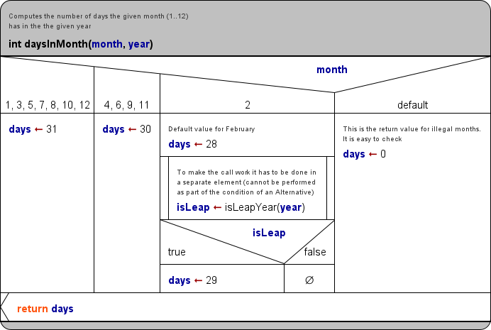
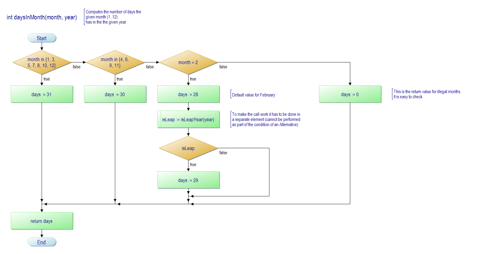
In order to watch the flowcharts or further process them you will of course have to install the compatible version of the PapDesigner application (≥ v2.2.0.8.06), which you can obtain from the project homepage or e.g. heise.de while some other third-party download pages may still offer an incompatible earlier version.
12. Logging
Since version 3.28-02, Structorizer makes use of the standard Java.util.logging mechanism to provide internal status information, error messages, warnings, and other diagnostic help in a configurable way. This page only refers to this general logging mechanism for Structorizer; be aware that some features (e. g. Code Import) provide addtional logging mechanisms, which are configured independently (see e.g. Import Options).
Location of the log files
The standard location of the log files is subfolder ".structorizer" of the user's home directory. If you are in doubt, you will find the actual paths of important folders or files on the "Paths" tab of the "About" dialog (which can be opened via the "Help" menu or key combination <Ctrl><F1>) in order to spare you from wild guessing (since version 3.28-10):

The log files match the name pattern "structorizer*.log" by default. But the exact naming scheme was modified with release 3.30 (though it did not become effective before version 3.30-08):
- Before release 3.30, the standard log file name was "structorizer0.log". In case of several concurrently running Structorizer instances, they used increasing "unique" numbers ("structorizer1.log", "structorizer2.log", etc.) lest they should merge their contents. There were no backups, and log entries may not have become visible before Structorizer was closed. By restarting Structorizer, the previous log file was immediately overwritten.
- Since release 3.30 (version 3.30-08, actually), the log files are named with two numbers, the "unique" number (as described above), and a "generation" counter as second number. The first log file will be named "structorizer0.0.log". In case of concurrent Structorizer sessions, they use differing first numbers ("structorizer0.*.log", "structorizer1.*.log" etc.). When Structorizer starts then it looks for the lowest unlocked unique (first) number; it will then rename all existing log files with this first number by incrementing the second number (e.g. "structorizer0.0.log" will become "structorizer0.1.log" etc.) before it creates its new log file with generation number 0. Hence: The larger the second number the older the log file. The obvious advantage of the file versioning is that restarting Structorizer does not destroy the previous log.
An empty file with additional extension ".lck" (e.g. "structorizer1.0.log.lck") signalizes that a Structorizer instance is logging to the corresponding log file and holds a handle of it. This will hinder other Structorizer instances opening it in parallel to mix in their logging data. Instead, these would use or create own log files with higher (first) number (e.g. "structorizer2.0.log").
On Structorizer startup, the logging parameters will be read from a file "logging.properties" (see section below), which is supposed to be placed in the log folder as discussed above. Among the parameters there are:
- the target folder for the log files (the very subfolder of the user home directory discussed above),
- the log file naming pattern (where placeholders "%h", "%u", "%g" designate the user home directory, the unique number, and the generation number, respectively, see above),
- the structure of the log entries (by default using an XML schema), and
- the minimum log level for which notifications are allowed to be logged (by default: CONFIG).
If you had already used Structorizer versions < 3.30 then you will have to remove the file "logging.properties" from the ".structorizer" folder in order to get the new configuration (if a configuration file is found then it will be preserved as it might contain a user-specfic configuration). Alternatively you might edit the existing configuration file manually (see below). The same holds with version 3.30-08, which corrects the naming scheme. (If your log files are named like "structorizer0.log.0" then you had obtained a flawed logging.properties file on installation, though this is not critical at all.)
Note: It may seem as if the logging information were written with some detention to the log file, the size of the file may be displayed as 0 in your file manager, even after a reported error. But don't get fooled. Just open the log file with some text viewer or editor — you will see that it actually contains log entries you may copy.
If you have restarted Structorizer after some misbehaviour that you would like to have analysed, the information will not immediately get lost: If the logging configuration is up to date, the logs of the last five sessions will still be maintained (their second number just gets incremented each time you close Structorizer and start it again, as explained above).
In Linux and OS X, the logging folder will usually be hidden (due to the naming scheme). So you may have to make it visible in order to inspect it, e.g. in Mac OS X you may have to press key combination <Shift><Cmd><H> in the Finder to show the home directory and then <Shift><Cmd><.> to make visible the directories and files named with an initial dot. With a GUI file manager in Linux, you might have to check an option "Show hidden files" in the "View" menu.
Logging content sample
The simplest log file content may look like this:
<?xml version="1.0" encoding="windows-1252" standalone="no"?>
<!DOCTYPE log SYSTEM "logger.dtd">
<log>
<record>
<date>2019-10-05T21:17:22</date>
<millis>1570303042244</millis>
<sequence>0</sequence>
<logger>Structorizer</logger>
<level>INFO</level>
<class>Structorizer</class>
<method>main</method>
<thread>1</thread>
<message>Command line: </message>
</record>
<record>
<date>2019-10-05T21:17:22</date>
<millis>1570303042416</millis>
<sequence>1</sequence>
<logger>lu.fisch.structorizer.gui.Mainform</logger>
<level>INFO</level>
<class>lu.fisch.structorizer.gui.Mainform</class>
<method><init></method>
<thread>1</thread>
<message>Structorizer 1 (version 3.30) starting up.</message>
</record>
<record>
<date>2019-10-05T21:17:22</date>
<millis>1570303042478</millis>
<sequence>2</sequence>
<logger>lu.fisch.structorizer.locales.Locale</logger>
<level>INFO</level>
<class>lu.fisch.structorizer.locales.Locale</class> <method><init></method> <thread>1</thread> <message>Loading now locale: en.txt</message>
</record>
<record>
<date>2019-10-05T21:18:04</date>
<millis>1570303084255</millis>
<sequence>22</sequence>
<logger>lu.fisch.structorizer.gui.Mainform</logger>
<level>INFO</level>
<class>lu.fisch.structorizer.gui.Mainform$4</class>
<method>windowClosing</method>
<thread>16</thread>
<message>Structorizer 1 (version 3.30) shutting down.</message>
</record>
As soon as you e.g. import a source file, however, or on certain trouble, you should expect many more entries (records) of different levels.
Logging configuration
The location of the file "logging.properties" is the ".structorizer" subfolder of the user's home directory (see discussion in "Location of the log file" above).
The default settings in the properties file are:
handlers= java.util.logging.FileHandler, java.util.logging.ConsoleHandler
(specifying that log records be written first to file and then to the console);
.level= INFO
(specifying that by default only log records with level INFO and more important are qualified to be logged as far as the respective log handler doesn't impose an even stricter filter);
java.util.logging.FileHandler.pattern = %h/.structorizer/structorizer%u.%g.log
java.util.logging.FileHandler.limit = 100000
java.util.logging.FileHandler.count = 5
java.util.logging.FileHandler.formatter = java.util.logging.XMLFormatter
java.util.logging.FileHandler.level = CONFIG
(configuring more specifically for the file logging:
- how log files be named and where to be placed,
- a maximum of 100000 bytes — which is about 100 KiB — per log file before logging rolls over to the next file,
- that at most 5 files (before release 3.30 it was only 1 file) be used for rotating log, which means overwriting the log file cyclically, — you may specify a larger number —,
- that the content of the log be formatted as XML, and
- that log records from level CONFIG on are principally allowed — which is more verbose than just INFO and already contains certain diagnosis records but requires that the default logging level is at least CONFIG, too).
java.util.logging.ConsoleHandler.level = SEVERE
java.util.logging.ConsoleHandler.formatter = java.util.logging.SimpleFormatter
(specifying that the console logging filter is raised to SEVERE — which means that nearly nothing is passed to the console, except very critical events —, and that the console messages use a very simple two-line format).
lu.fisch.structorizer.parsers.level = CONFIG
(specifying that on source code import the general log level threshold of INFO is lowered to CONFIG — thus including some developer diagnostics for those logging handlers — file or console — being open for it.)
You find more detailled information about logging configuration in the official Java documentation.
Your individual settings in this file will be preserved, even on updating Structorizer to a new version. If you want to get back to the original default settings of Structorizer or, contrarily, update to the new configurations of release 3.30 then just rename or delete the file "logging.properties" before you start Structorizer the next time — Structorizer will then create an new default configuration file in the ".structorizer" folder.
Use of logging results
After some functional problem in Structorizer or a crash, you may rescue (i.e. copy) the respective log file from the ".structorizer" folder and pass it with the bug report for further analysis to the Structorizer development team.
Be aware that the log file might be incomplete while Structorizer is still running (as mentioned above). You should avoid opening Structorizer again before you have copied the log file because starting Structorizer may override an existing log file.
Data protection (privacy) remark
Log files won't contain personal data or sensitive data about your machine. But they might contain file paths and therefore user account names. So you can of course review the contents and make sure there aren't privacy risks before you upload or e-mail them — the file contains XML by default (or plain text if you specify e.g. "java.util.logging.SimpleFormatter" as formatter). If you decide to clear some information you don't want to share, then you should of course preserve the well-formed XML structure.
13. Key bindings
Besides the usual key bindings for copy (ctrl c), cut (ctrl x), paste (ctrl v), help (F1), quit (ctrl q) etc., the tables show more specific accelerator keys provided by Structorizer.
Insert elements into the diagram
| Function | after current element | before current element |
| insert Instruction |
F5 |
shift F5 |
| insert IF Statement |
F6 |
shift F6 |
| insert CASE Statement |
F10 |
shift F10 |
| insert FOR Loop |
F7 |
shift F7 |
| insert WHILE Loop |
F8 |
shift F8 |
| insert REPEAT Loop |
F9 |
shift F9 |
| insert ENDLESS Loop |
ctrl F7 (≥ V 3.29-13) |
shift ctrl F7 (≥ V 3.29-13) |
| insert CALL |
F11 |
shift F11 |
insert EXIT (Jump)
|
F12 |
shift F12 |
| insert PARALLEL |
ctrl F6 (≥ V 3.29-13) |
shift ctrl F6 (≥ V 3.29-13) |
| insert TRY Block |
ctrl F5 (≥ V 3.29-13) |
shift ctrl F5 (≥ V 3.29-13) |
Work with selected elements in the diagram
Work with Structorizer or the entire diagram itself
| Function | Accelerator key |
| scroll one screen up |
pageUp |
| scroll one screen down |
pageDown |
scroll one screen left (≥ V 3.29)
|
shift pageUp |
scroll one screen right (≥ V 3.29)
|
shift pageDown |
go to top left (≥ V 3.29)
|
home |
go to bottom right (≥ V 3.29)
|
end |
| open user guide (in browser) |
F1 |
| show version info |
shift F1 |
| show link to the home page |
ctrl F1 |
create new diagram (clear diagram)
|
ctrl n |
| open (load) a diagram |
ctrl o |
| save diagram |
ctrl s |
| save diagram as... |
ctrl alt s
|
| save all diagrams |
ctrl shift s |
| undo last change |
ctrl z |
| redo last undone change |
ctrl shift z, ctrl y |
| print diagram |
ctrl p |
| copy as EMF image to clipboard |
ctrl shift d |
| copy as PNG image to clipboard |
ctrl d |
| create PNG image file |
ctrl e
|
| open the Find & Replace dialog |
ctrl f |
| open Executor control ("run") |
ctrl r |
| open Turtleizer and Executor control |
ctrl shift r |
| export as program code for preselected language |
ctrl shift x |
| open Attribute Inspector |
alt enter |
| toggle text and comment view |
ctrl alt v |
highlight syntax (on/off)
|
F4 |
switch structogram analysis on or off
|
F3 |
show/hide Arranger index
|
shift F3 |
| show/hide Code preview (≥ V 3.30) |
shift F4 |
enlarge font
|
ctrl Numpad+ |
diminish font
|
ctrl Numpad- |
move horiz./vertical divider with cursor keys
|
ctrl F8 |
circle focus clockwise (also ends divider mode)
|
tab |
circle focus counter-clockwise
|
shift tab |
Font resizing in other contexts
Arranger index and Analyser report area
| Function | Accelerator key |
scroll up (≥ V 3.29)
|
↑ (+shift: 10 x speed) |
scroll down (≥ V 3.29)
|
↓ (+shift: 10 x speed) |
scroll left (≥ V 3.29)
|
← (+shift: 10 x speed) |
scroll right (≥ V 3.29)
|
→ (+shift: 10 x speed) |
move selected up (≥ V 3.29)
|
ctrl ↑ (+shift: 10 x speed) |
move selected down (≥ V 3.29)
|
ctrl ↓ (+shift: 10 x speed) |
move selected left (≥ V 3.29)
|
ctrl ← (+shift: 10 x speed) |
move selected right (≥ V 3.29)
|
ctrl → (+shift: 10 x speed) |
scroll one screen up (≥ V 3.29)
|
pageUp |
scroll one screen down (≥ V 3.29)
|
pageDown |
scroll one screen left (≥ V 3.29)
|
shift pageUp |
scroll one screen right (≥ V 3.29)
|
shift pageDown |
go to left margin (≥ V 3.29)
|
home |
go to right margin (≥ V 3.29)
|
end |
go to top (≥ V 3.29)
|
ctrl home |
go to bottom (≥ V 3.29)
|
ctrl end |
zoom in
|
Numpad+ |
zoom out
|
Numpad- |
switch the Zoom button from zoom out to zoom in
and the Drop Diagram button to Remove All
|
shift |
remove the selected diagrams
(with confirmation request, ≥ V 3.29)
|
del |
remove the selected diagrams
(without confirmation request, ≥ V 3.29)
|
ctrl del |
cut the selected diagram
|
ctrl x, shift del |
copy the selected diagram to the clipboard
|
ctrl c, ctrl ins |
paste a diagram from the clipboard
|
ctrl v, shift ins |
| select all diagrams (≥ V 3.29) |
ctrl a |
expand the selection to all directly or indirectly
referenced diagrams (≥ V 3.29)
|
F11 |
make a group from the selection (≥ V 3.29-01)
|
ctrl g |
expand the selection and make a group from it (≥ V 3.29-01)
|
ctrl shift g |
save the arrangement of the selected diagrams
(≥ V 3.29) |
ctrl s |
load an arrangement from file (≥ V 3.29)
|
ctrl o |
rearrange all diagrams by groups (≥ V 3.29-01)
|
ctrl r |
open the Arranger help page in browser
(≥ V 3.29)
|
F1 |
open the Arranger key bindings page (this table) in browser
(≥ V 3.29)
|
alt F1 |
| Function | Accelerator key |
find next
|
alt n
|
replace
|
alt r
|
downward search
|
alt d
|
upward (reverse) search
|
alt u
|
toggle "Case sensitive"
|
alt c
|
toggle "Whole word"
|
alt w
|
toggle "Regular expressions"
|
alt x
|
toggle "Element-wise"
|
alt e
|
close
|
esc
|
| Function | Accelerator key |
load the locale of the selected button
|
enter |
re-load a language file for the selected locale
|
shift enter |
open the Find dialog
|
ctrl f |
Note: Instead of the ctrl key you may have to use an OS-specific default command key. Mac users, for example, may have to press the "Apple command key" ( ) instead of the ctrl key in some of the respective key bindings ...


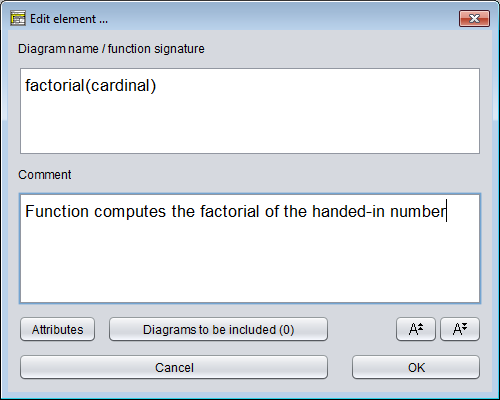
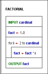
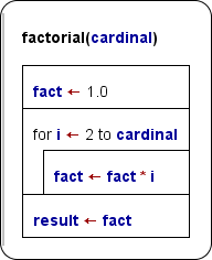


 Moves the selected rows one row down.


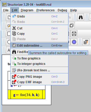
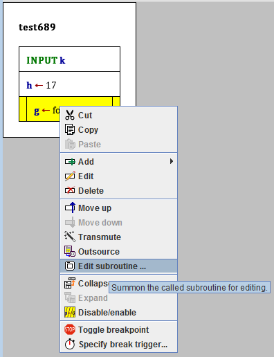


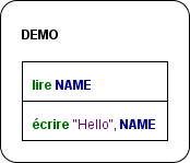
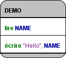
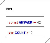
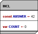


 ==>
==> 


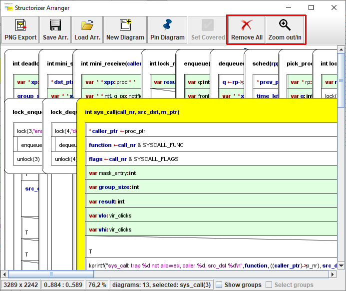


 Arranger help ... (or


 Export diagram/group (new since version 3.30-07)


